Key : 🔹 discussion 🔸 lecture ⚡ demo/activity 🍕 lunch
⚡ Arduino 201 and Sound Circuits
- analog input
- using tone() for sound
- LilyPad as HID keyboard creating sound from computer
🔹 One-on-one discussions of final project ideas
⚡ Start 1st prototype
- prototyping techniques
H.W. start 1st prototype
——————–
Arduino 201
Reading Analog Input
In the hybrid lab, soldering to the delicate pins of a flex sensor or FSR aren’t a good idea. A way to make a temporary connection is be using female headers soldered to the end of two wires.

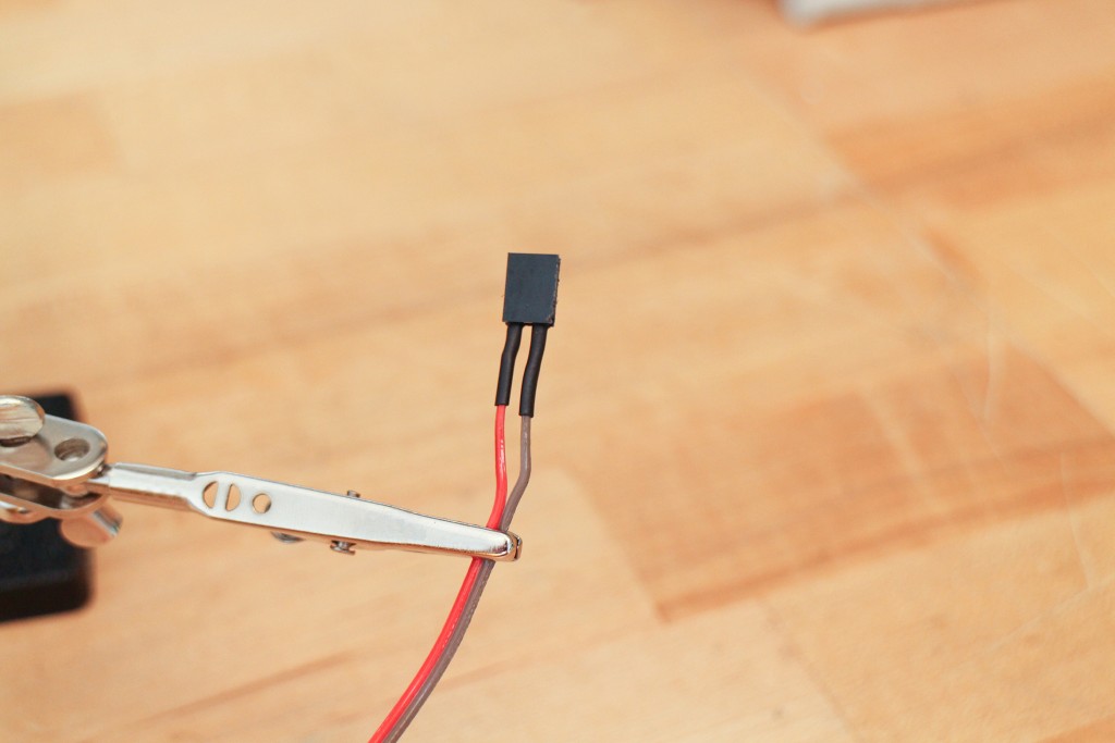
two female headers ready to be soldered to wire
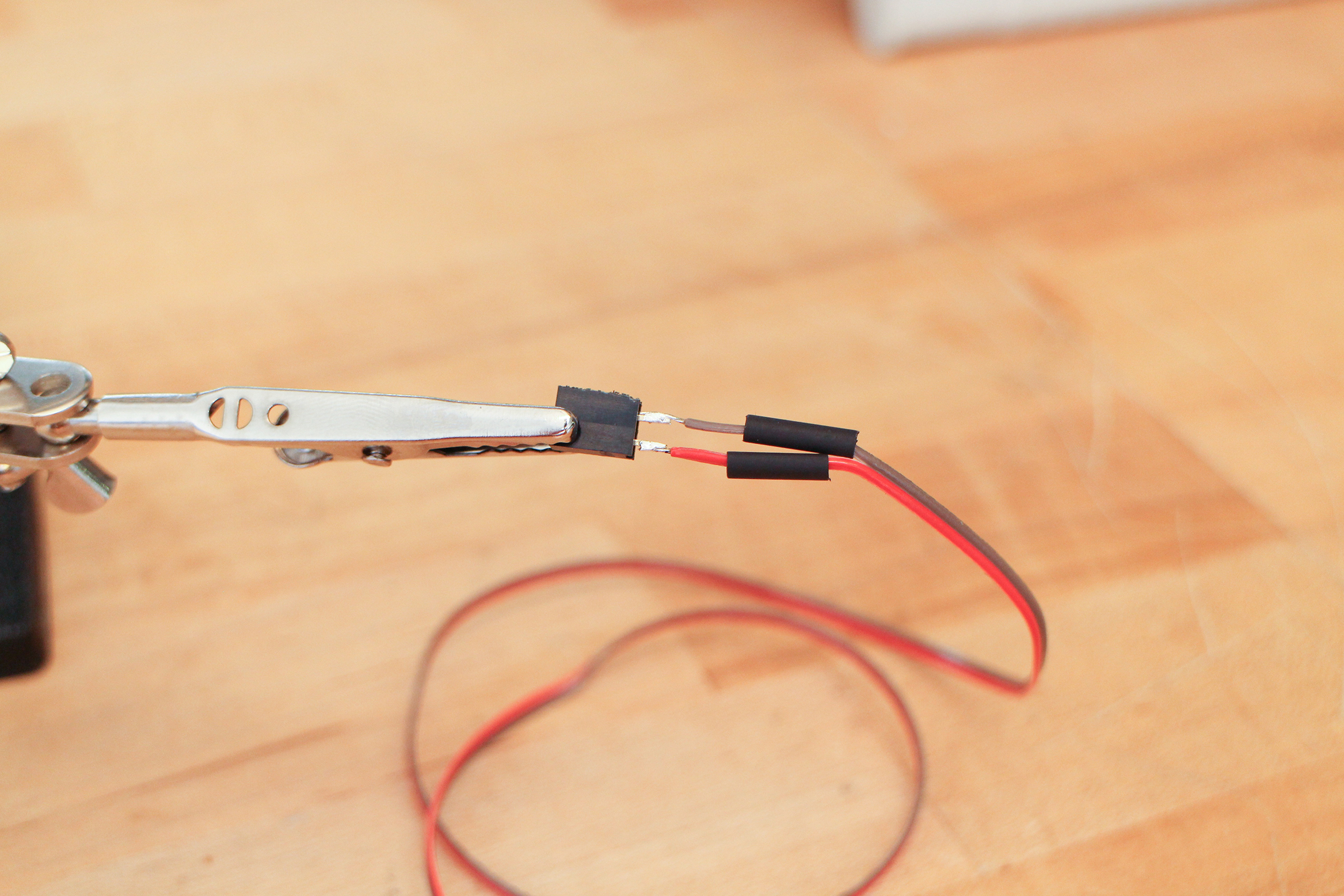
soldered with heat shrink tubing ready to shrunken with the heat gun!
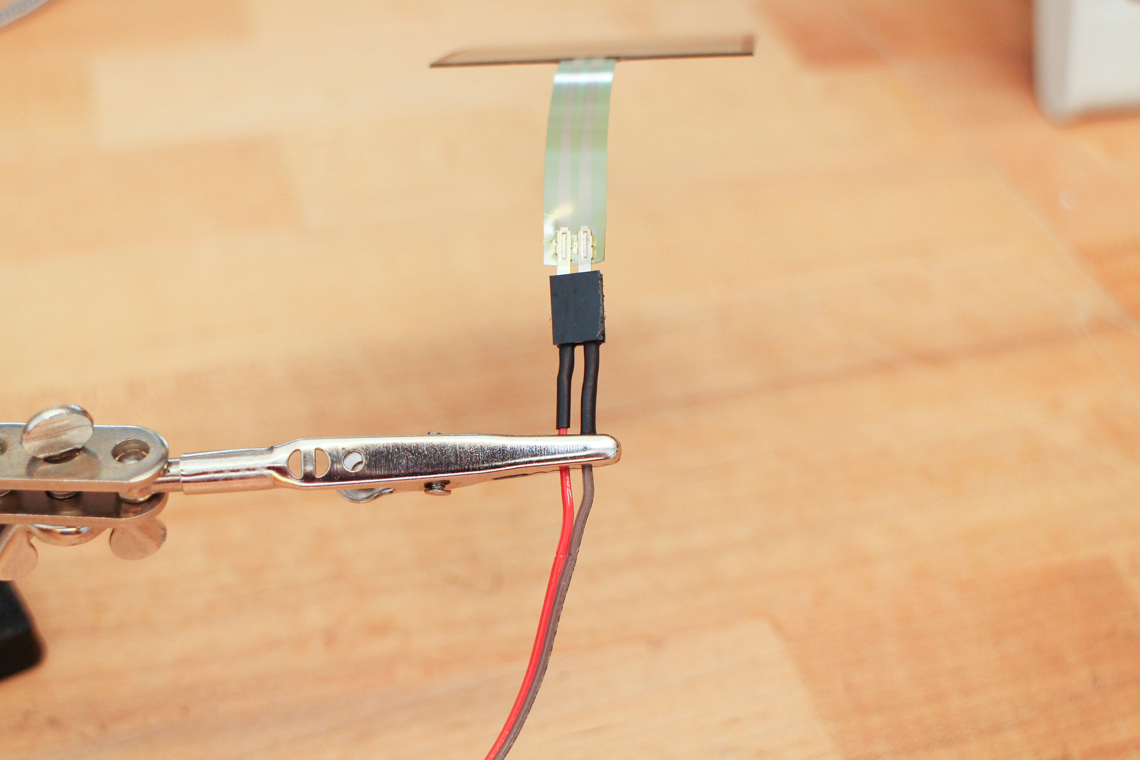
Plug in the flex or force sensor
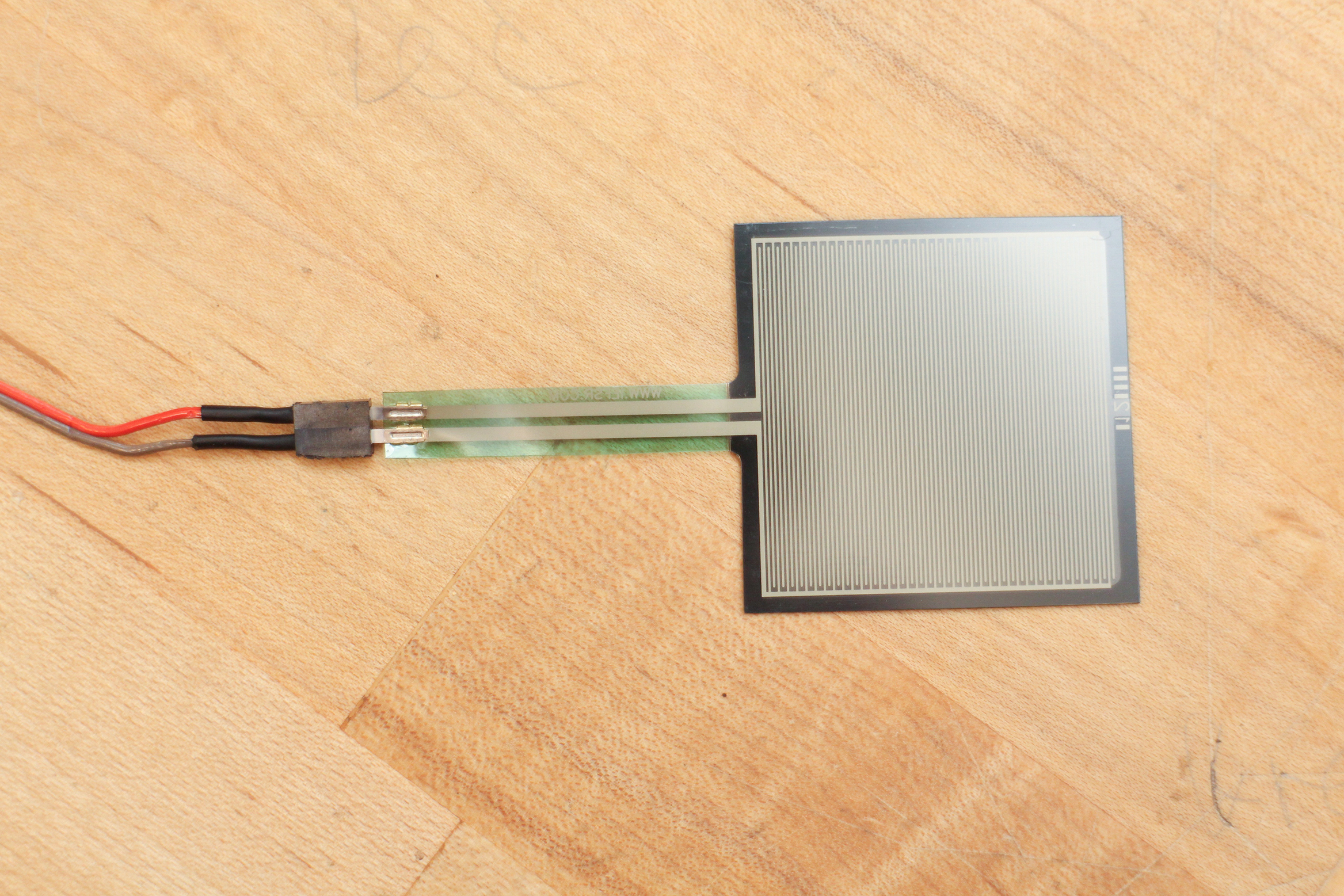
wrap the part where the connect with some tape. The connection won’t hold very long without.
Solder two female headers to ribbon wire.
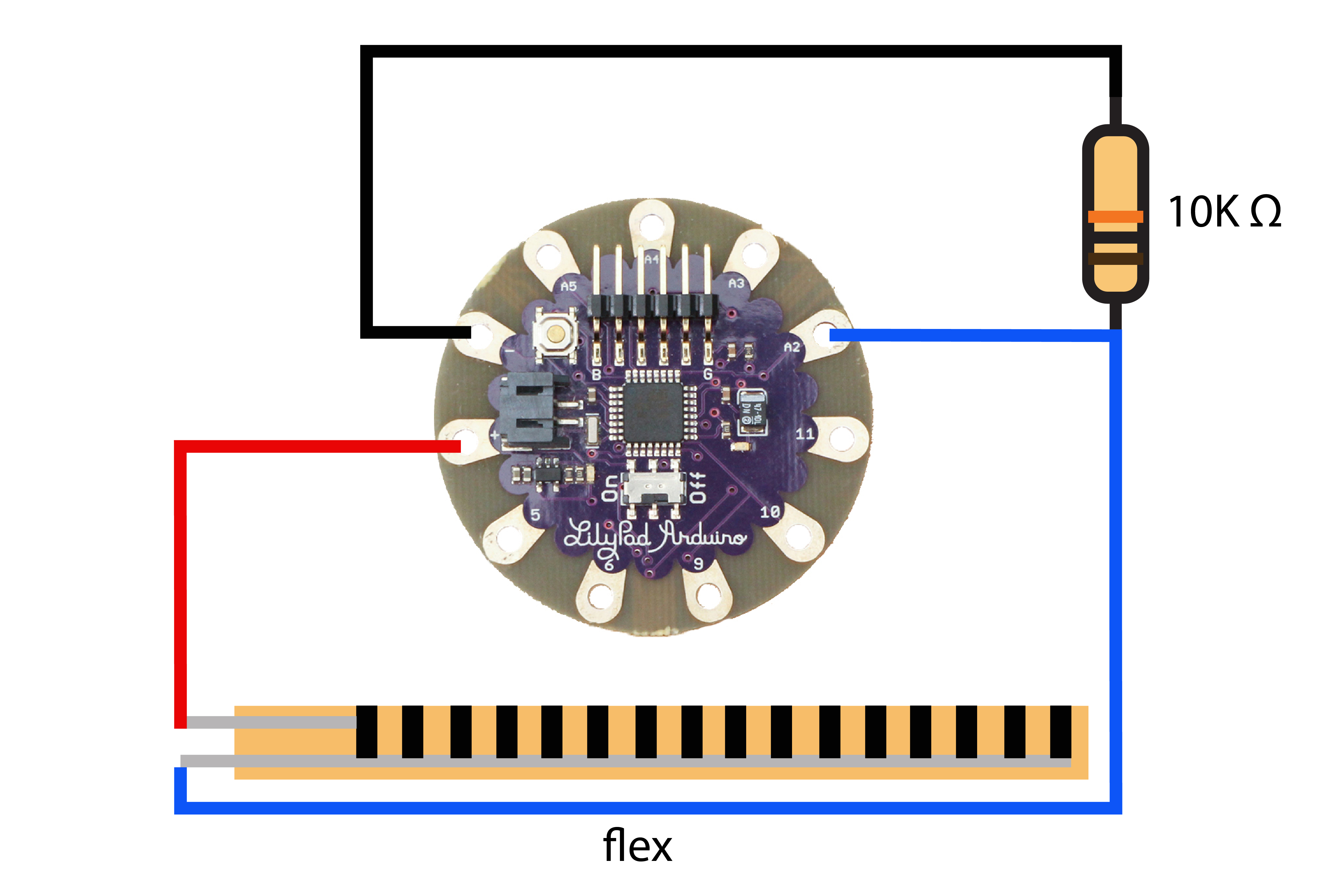
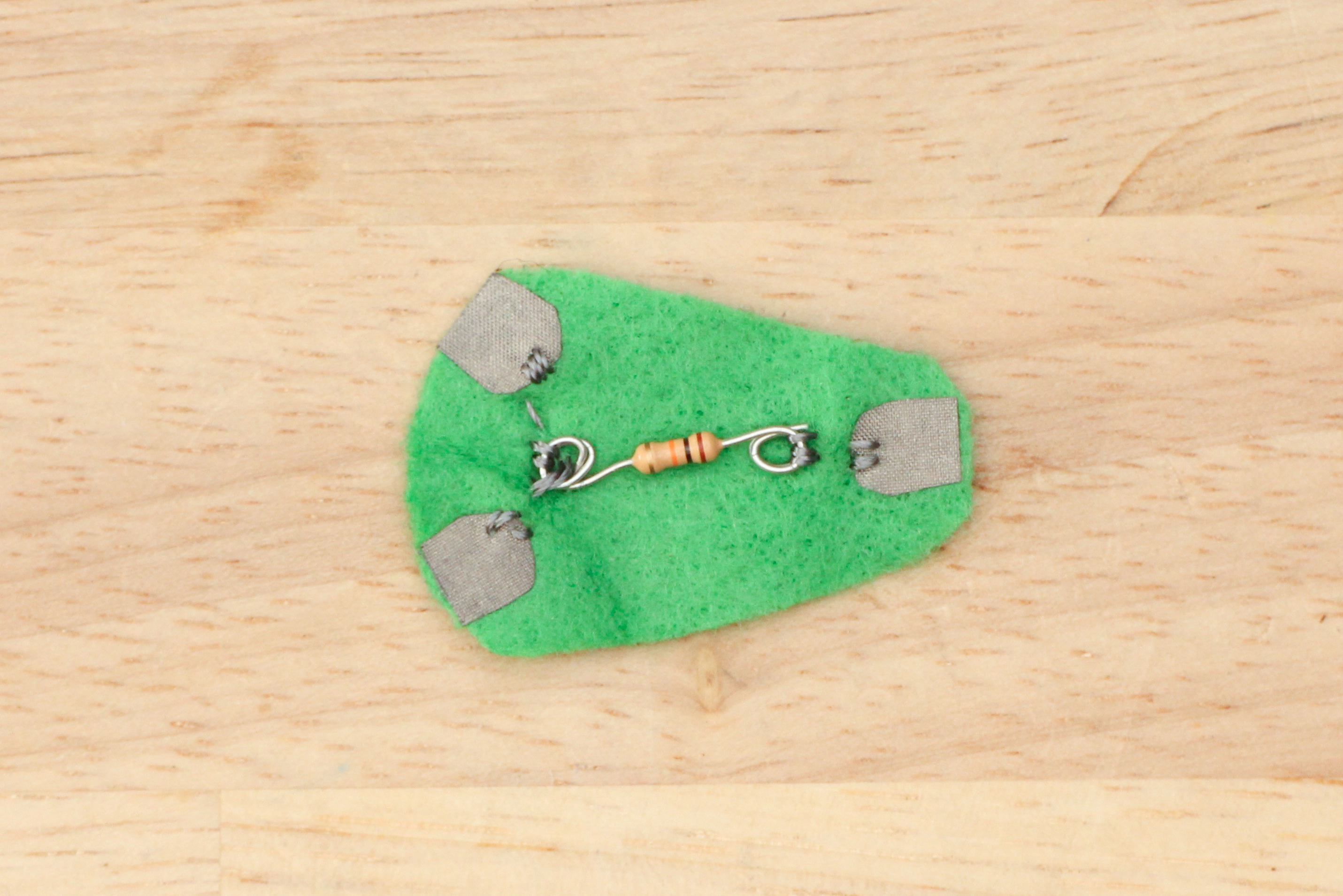
Connect the circuit as illustrated with alligator leads. You can sew and use a resistor pad to clip to, it makes the resistor easier to identify and connect to when clipping together a circuit.
Open up the Arduino program and navigate to File -> Examples -> Basic -> AnalogReadSerial
Change the pin number to A2.
|
1 |
int sensorValue = analogRead(A2); |
Choose your board and serial port. Upload.
Open the serial window by clicking the button in the upper right corner that has a magnifying glass on it. If you hover over a button, it will also identify itself.
You should be getting a string of values. If you don’t interact with the sensor, it will be at it’s highest value. Pick it up and bend and watch the number go down. This is how you sense it bending, capturing this range of values and using the data to trigger events. Write down the highest number when your sensor is resting and the lowest number you get when you bend it to its limit.
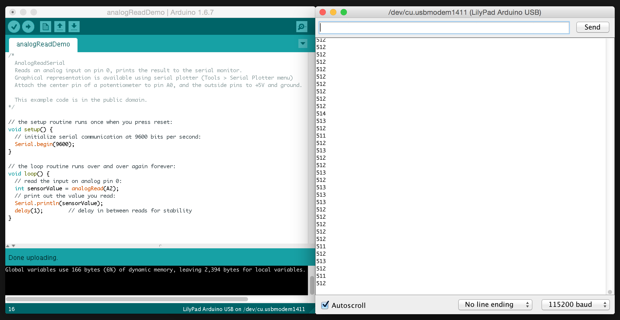
Mine where:
High (resting state) = 520
Low (bent) = 260
Flex Sensor Playing Note Using a Threshold
Keep the sensor hooked up to A2.
Take a speaker, connect one side to pin 2 and the other to ground.
Copy and paste this sketch in a new window and save.
|
1 2 3 4 5 6 7 8 9 10 11 12 13 14 15 16 17 18 19 20 21 22 23 24 25 26 27 28 29 30 31 32 33 34 35 |
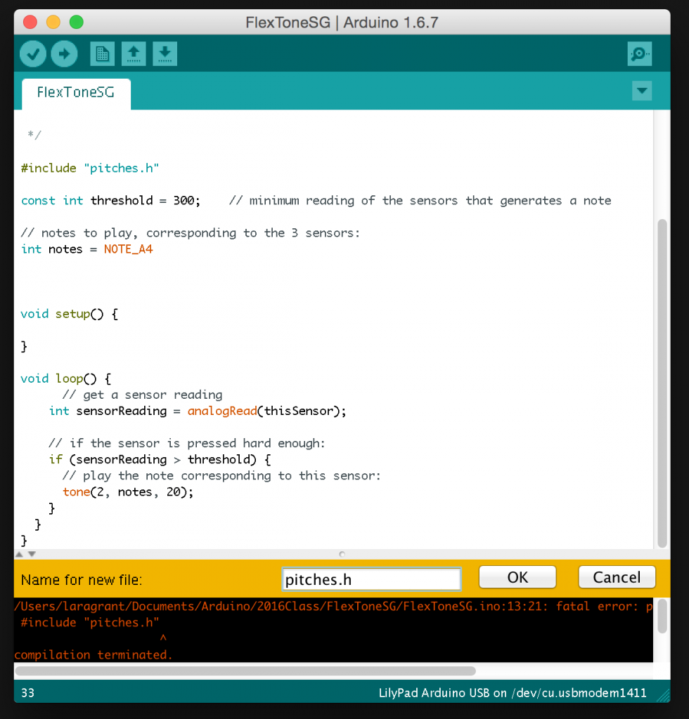
/* Plays a note when flex sensor reaches certain threshold circuit: * 1 flex sensor from +5V to A2 * 1 10K resistors from A2 to ground * speaker on digital pin 2 */ #include "pitches.h" const int threshold = 300; // minimum reading of the sensors that generates a note const int flexOne = A2; const int speakerPin = 2; // note to play int note = NOTE_A4; void setup() { Serial.begin(9600); } void loop() { // get a sensor reading int sensorReading = analogRead(flexOne); // print sensor value to serial window Serial.println(sensorReading); // if the sensor is pressed hard enough: if (sensorReading < threshold) { // play the note corresponding to this sensor: tone(speakerPin, note, 20); } } |
If you try to upload, you will get an error that a file doesn’t exist or is missing:
pitches.h
At the very top of the sketch we tell it to reference the file, but using #include.
|
1 |
#include "pitches.h" |
Click the button in the upper right corner that has a downward arrow on it. It is below the serial window button. Choose New Tab
.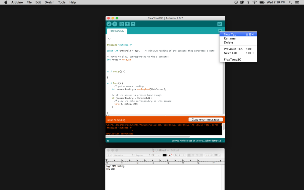
Name it pitches.h
Click the link, copy the code and paste in the new pitches.h tab.
pitches.h

The pitches.h file assigns numbers to the name of the note that it will play. For example:
|
1 |
#define NOTE_CS1 35 |
35Hz will produce the note C sharp in the 1st octave, so that is the value being assigned to that variable.
#define is another way to declare a
|
1 |
const |
variable.
Upload the sketch and open the serial window to watch your sensor values.
Bend the sensor and listen for your note!
Changing Pitch with Flex Sensor
This next exercise changes the pitch of the note as the flex sensor is bent, instead of triggering one note with one pitch when it bends to a certain degree.
There is an example sketch that you can work from. Open Arduino and navigate to File -> Examples -> Digital -> PitchFollower
Connect sensor to A2 with a voltage divider resistor of 10K ohm.
Connect speaker to pin 9.
Change the pins in example code to reflect.
|
1 |
int sensorReading = analogRead(A2); |
|
1 |
tone(9, thisPitch, 10); |
Go ahead and upload at this point, bend and listen to the behavior of the note and pitch playing out of the speaker. It may sound off or wrong. This is probably because the values need to be changed in the map () function and tuned to the high and low values of your sensor that you discovered in the previous exercise.
If you need to read them again, open the serial window and you will see your values printing out there.
Map()
map (sensor pin number, from Low, from High, to Low, to High);
The map function takes out sensor low and high value and maps them to a range of new values that translates better to the frequency of a note. Our sensor’s low and high are about 260 – 520, and the output pitch range is 120 – 1500 Hz. You want to drop the new value range in a variable, which we are calling:
|
1 |
int thisPitch |
So you can use the map function like this:
|
1 |
int thisPitch = map(sensorReading, 260, 520, 120, 1500); |
Adjust the pitch range as you like, 1500 Hz produces some high pitches.
Combining Threshold with Pitch Follower
Notice how as soon as you upload the sketch the note starts playing. After some time, you realize it would be nice to control when the note started playing. You can do this by adding a button and telling it to start playing when pressed, or you can use the sensor too, and use the If statement used in the threshold example.
Open up a new sketch, copy and paste the code below.
|
1 2 3 4 5 6 7 8 9 10 11 12 13 14 15 16 17 18 19 20 21 22 23 24 |
const int threshold = 450; // minimum reading of the sensors that generates a note const int flexOne = A2; const int speakerPin = 9; void setup() { Serial.begin(9600); } void loop() { // get a sensor reading int sensorReading = analogRead(flexOne); // print the sensor reading Serial.println(sensorReading); int pitch = map(sensorReading, 280, 520, 120, 1000); // if the sensor is bent enough play note and pitch bend // with sensor if (sensorReading < threshold) { tone(speakerPin, pitch, 20); } delay(1); } |
This is where you are telling it to play the note and change the pitch based on the sensor reading IF the value goes less than 450.
|
1 2 3 |
if (sensorReading < threshold) { tone(speakerPin, pitch, 20); } |
Notice how I didn’t mention that we needed the pitch.h file? This is because we are using the number of Hertz instead of the variables declared in the pitches.h file. So, there is no need to add it.
Voltage Divider Circuit
Take a look at the circuit above, the 10K resistor in the circuit is a very important part of the circuit and makes it so the changing resistance of the sensor is read by the microcontroller. The circuit that the 10K resistor and the flex sensor (which is a variable resistor) make is called a voltage divider. Simply put, this is how it works – the circuit takes a large amount of voltage and reduces it to a smaller amount. The voltage is divided by the two resistors in series and the amount it is reduced to is in relation to the value of the resistors.
The flex sensor and other sensors like a photocell and FSR change resistance, you can read this on your multimeter on the ohm setting. The flex sensor changes resistance in proportion to how much it’s bent. Unlike the multimeter the microcontroller does not read the changing resistance, but it can read changing voltage.
Using a voltage divider circuit allows us to read the point where the voltage is divided and this is how we are able to read resistive sensors. The voltage is read by the microcontrollers analog-to-digital converter or ADC.
How do we know what voltage we will get or what resistors to use? Here is the equation that can help us do that.
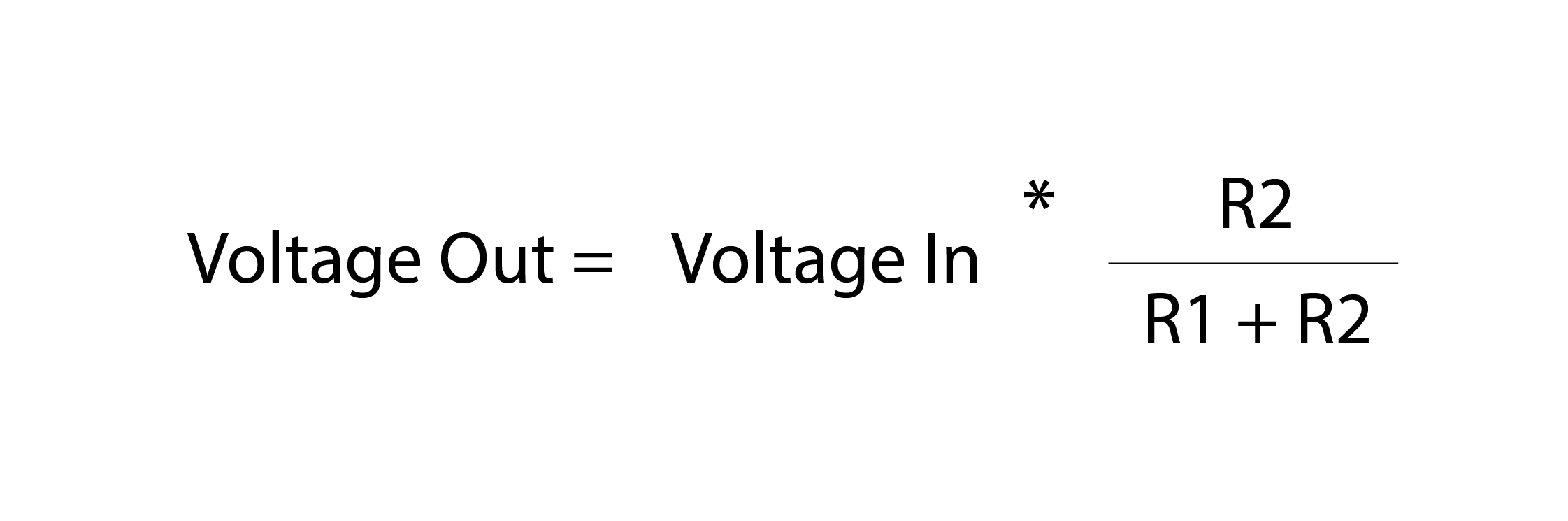
Let’s take a look at the circuit of it’s built with a flex circuit and microcontroller. The left schematic shows where R2, R1, voltage in and out are situated. The right schematic puts components in place, a flex sensor, 10K ohm resistor, what the voltage out is hooked up to and where the voltage in comes from. The microcontroller provide you with 5volts from it’s power pin.
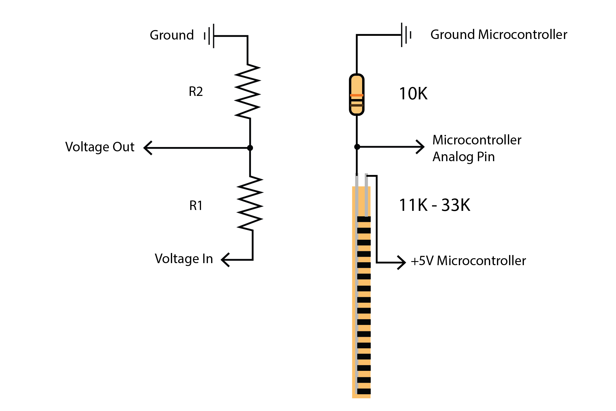
There is a 10K in the circuit above where R2 is, how was that picked? There are a couple general rules that helps when choosing the R2 resistor, which is:
- If R2 is much larger than R1, the output voltage will be close to the input (5V).
- If R2 is much smaller than R1, the output will be a tiny portion of voltage, closer to 0V.
Tone() is a good introduction to what an Arduino board can do on it’s own with the available memory it has, but there are other ways to make noise with a microcontroller.
Check out some ways to do that on the Making Noise with Microcontrollers page.