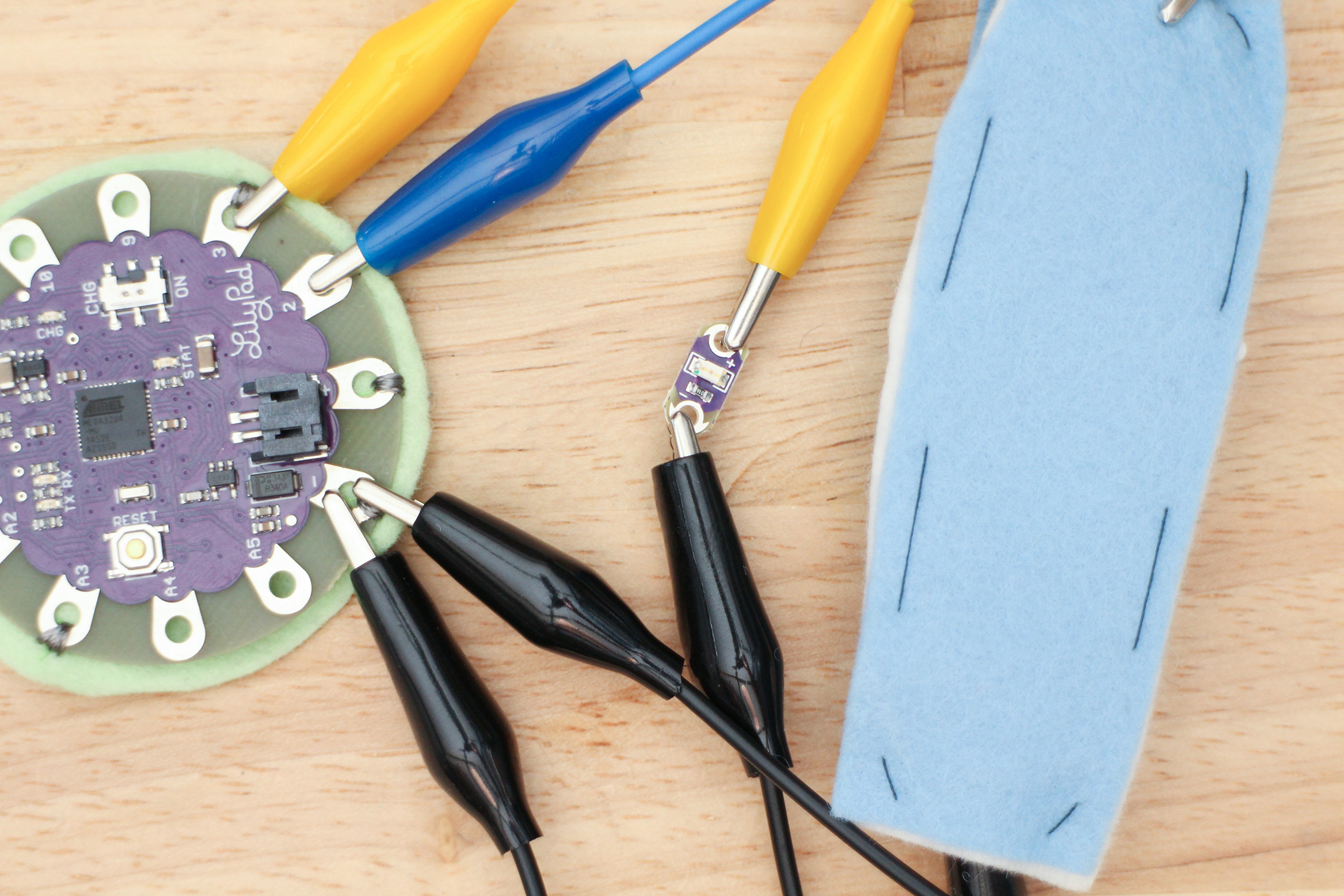
So, your circuit is working and you are ready to go to the next step in the prototyping phase, getting the circuit onto the fabric. Your circuit will be clipped together with alligator leads at this point. You have also been using the computer for power through the USB port while you have you testing and uploading your sketches. This is about to change and your circuit is about to go mobile.

Clipped together working circuit ready to put onto fabric.
Record Circuit
Before you move on and eventually take apart your circuit, grab a piece of paper and a pen.
Record each connection that is made, you will refer back to this when rebuilding the circuit on fabric. You can do this in a few different ways. You can draw a block diagram, a schematic or line-by-line, like this.
Component LilyPad
Switch –> pin 2
Switch –> ground
LED power (+) –> pin 3
LED ground (-) –> ground
You can also use Fritzing, a software that let’s you make circuit diagrams using graphics of the components. Double check the circuit with what you recorded before taking it apart.
Place Components
Disassemble your circuit and gather all your components and parts. For my circuit, this is what I have:
1 x LilyPad microcontroller
1 x battery
1 x LED
1 x handmade switch
The handmade switch already has a place to live, I’ve decided to put that on the ball of hand previously through observing a high-five and deciding placement based on where a high-five is most likely to close it.
That leaves me with 4 components to figure out the placement of. The arrangement of components can be influenced by several things. Many will be based on choices you are making for the wearer on how they will experience your design, some are good wearable electronic circuit design practices.
From User POV
Below are topics pertaining to the user experience, with examples of how these topics apply.
Comfort
- will the microcontroller inhibit wrist movement if I place it on the wrist?
Function
- will the user be able to reach the button or see the LED?
Balance (with larger piece of fabric and heavy components)
- will the weight of my battery interfere with the drape of my fabric?
Aesthetic
- does the arrangement fit my aesthetic standards and communicate what I need to the user?
Good Practice
When placing components, keep these things in mind as a good practice.
- Place your components so the pads that need to connect can access each other easily and without crossing too many other conductive paths.
- Figure out where the battery will go and how it will connect to the microcontroller, it can easy to forget about when developing the circuit while connected to the computer.
- Your power and ground lines between the battery and circuit want to be as short as possible if using conductive thread. Why? Because conductive thread has resistance and adds up over distance. Imagine if you have an LED connected to the battery, the battery is on your hip and the LED is on your ankle and they are connected by conductive thread. The battery is 3v and the LED is rated as needing 2.8 – 3 volts to operate. Some conductive thread has a resistance of 14 ohms per foot, let’s say you used a zigzag stitch down the leg, totaling about 4 feet of thread between the battery and LED. Four feet of the thread equals 56 ohms, the LED may be dimmed by this, or cause it to not light at all. This can also take away some current you will need for the rest of the circuit.
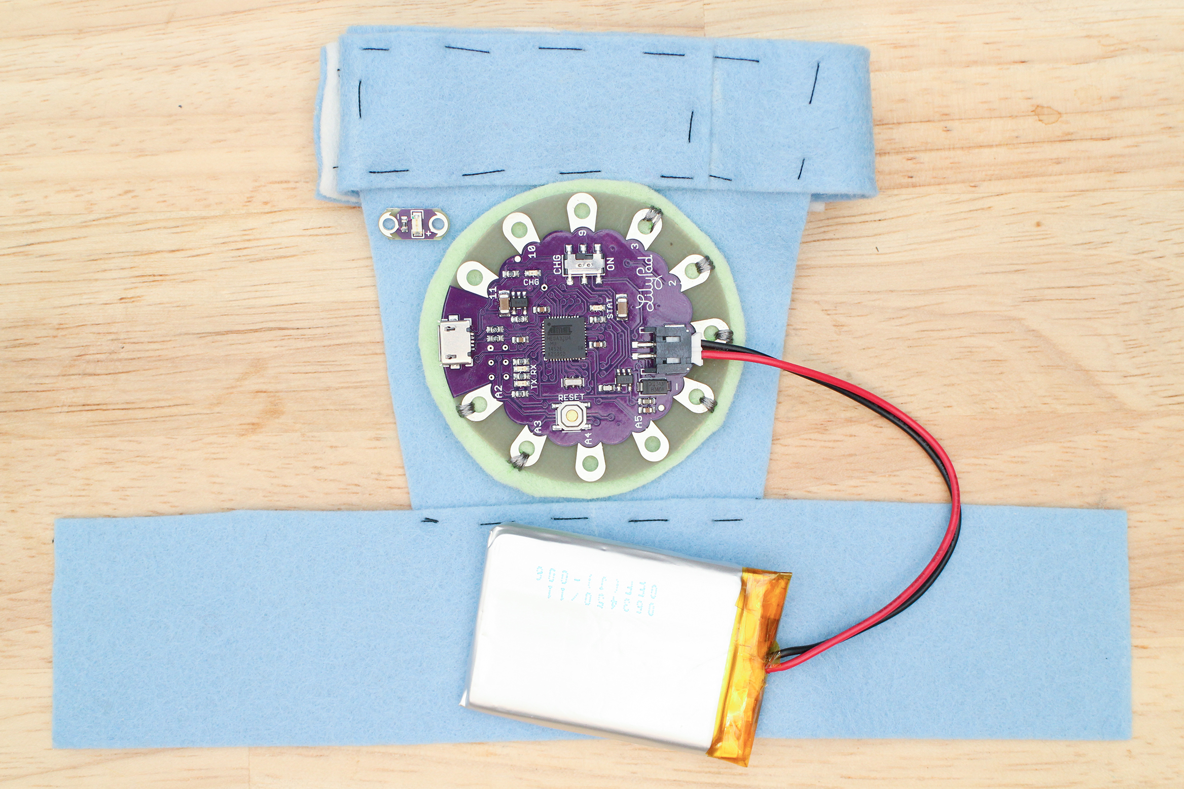
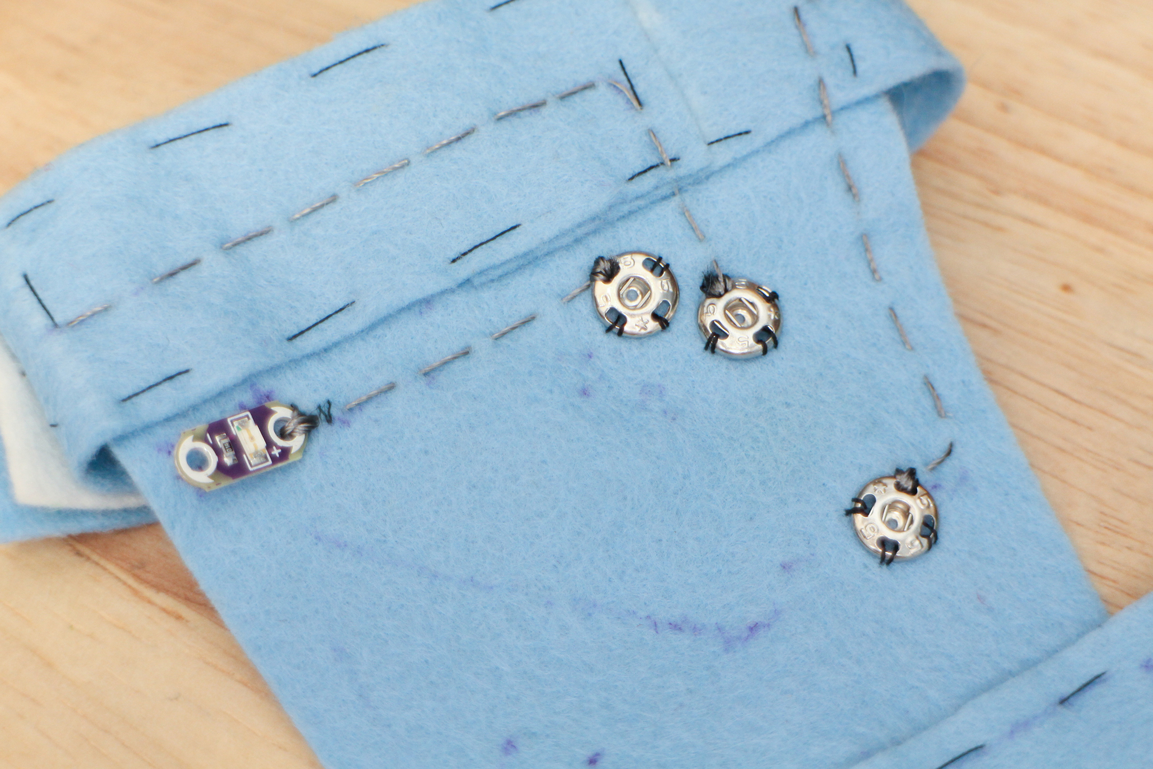
microcontroller, LED and battery laid out on fabric prototype. I put the board’s USB port somewhere it can be accessed easily in case I want to upload sketches once it’s attached. Battery is clipped in, with the board power switch off, so I can make sure it can connect to the battery easily.

Using a disappearing and water soluable pen to trace the outline of each component.
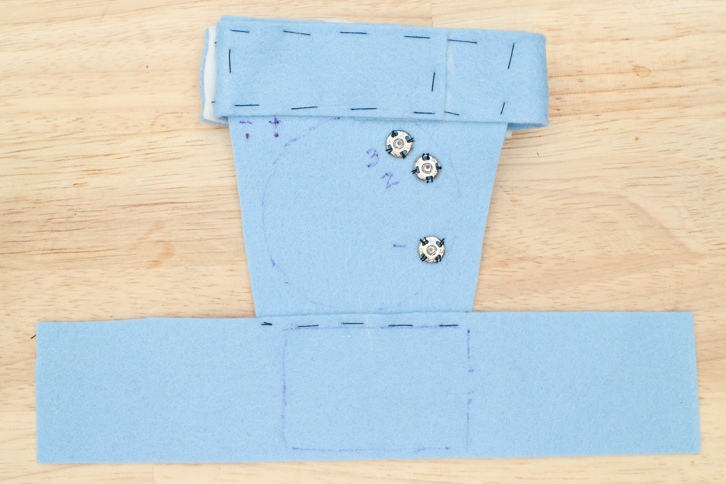
Outlines traces with pins marked. The LED + and – are marked on the LED as well as pin 2, 3 and the ground pin of the microcontroller. Where the power and ground lines of the battery come from are marked in case I need to know that later on when building the circuit.
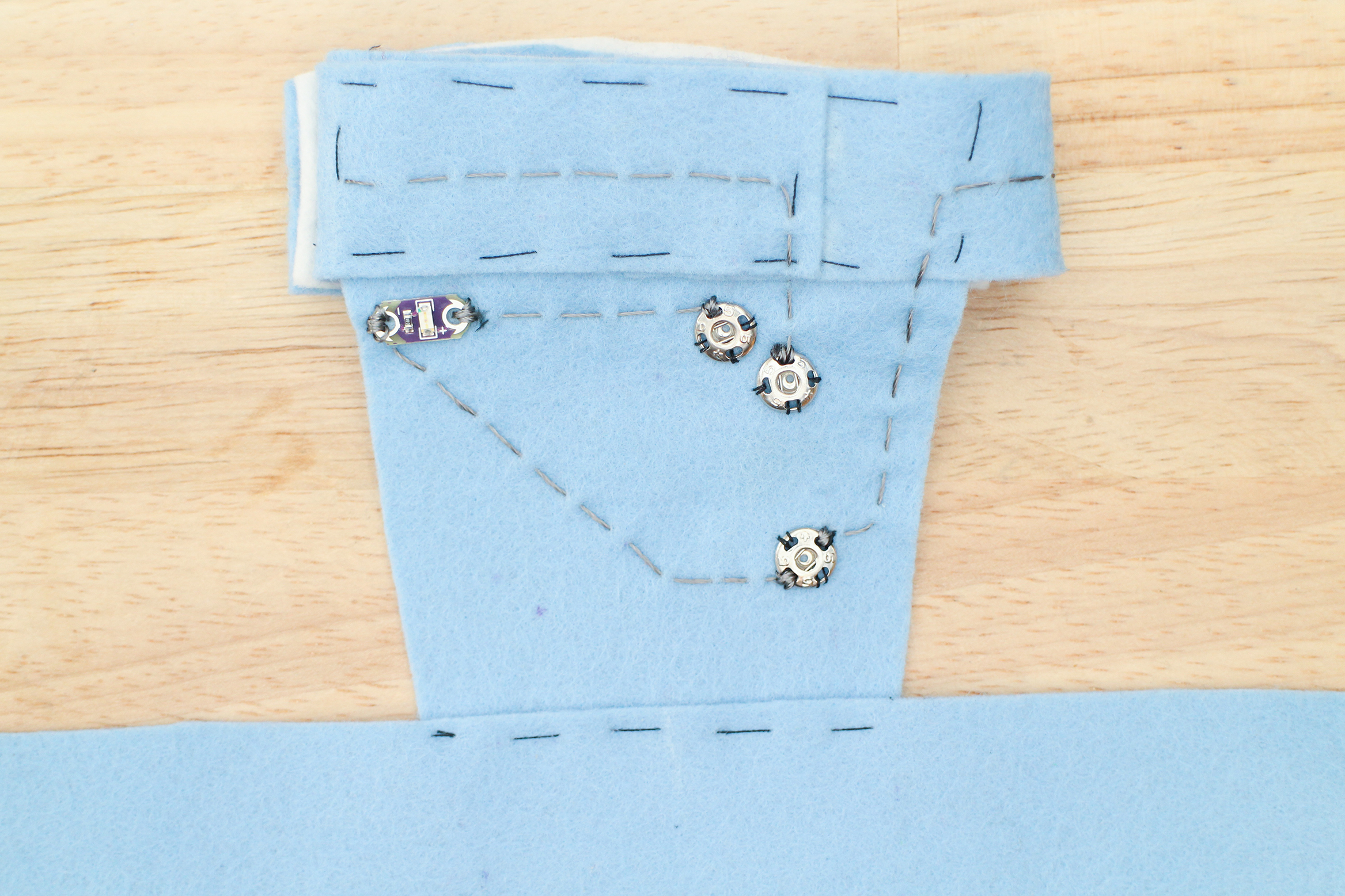
Draw in Circuit
Refer to the connections you recorded before you took everything off the alligator leads.
Start to draw in each connection.
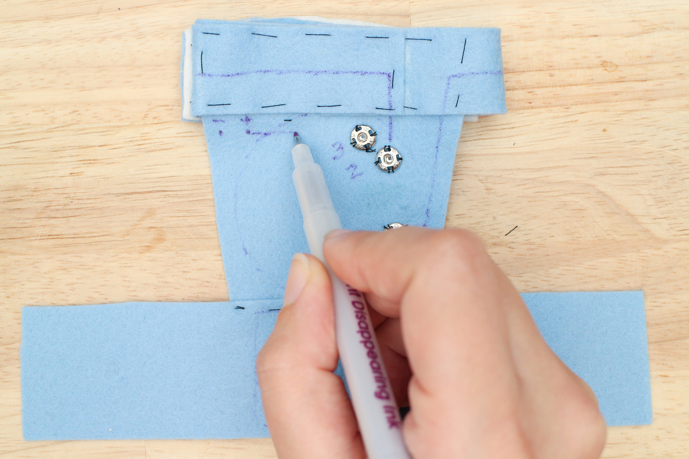
Connections from the switch on the palm side to the microcontroller are already drawn in. Drawing in the connection from LED + pin to pin 3 of LilyPad.
Notice how the traces going from LED ground and power pin to the microcontroller pins are going within the boards ouline. This means the traces will be under the board.
Under the microcontroller or a component can offer you more real estate for your traces. Just beware of creating a short circuit. The conductive thread or fabric may touch two open metal spots on the bottom of the board, causing a short. Double check to see if there is danger of that before drawing and making your trace.

All traces draw in.
Build Circuit on Fabric
To build your circuit on fabric, you have a choice of some soft conductive materials. The two you will be choosing from are conductive thread and conductive fabric. The thread gets sewn into the fabric, the fabric get’s ironed on. Below you will see examples of a sewn conductive thread circuit.
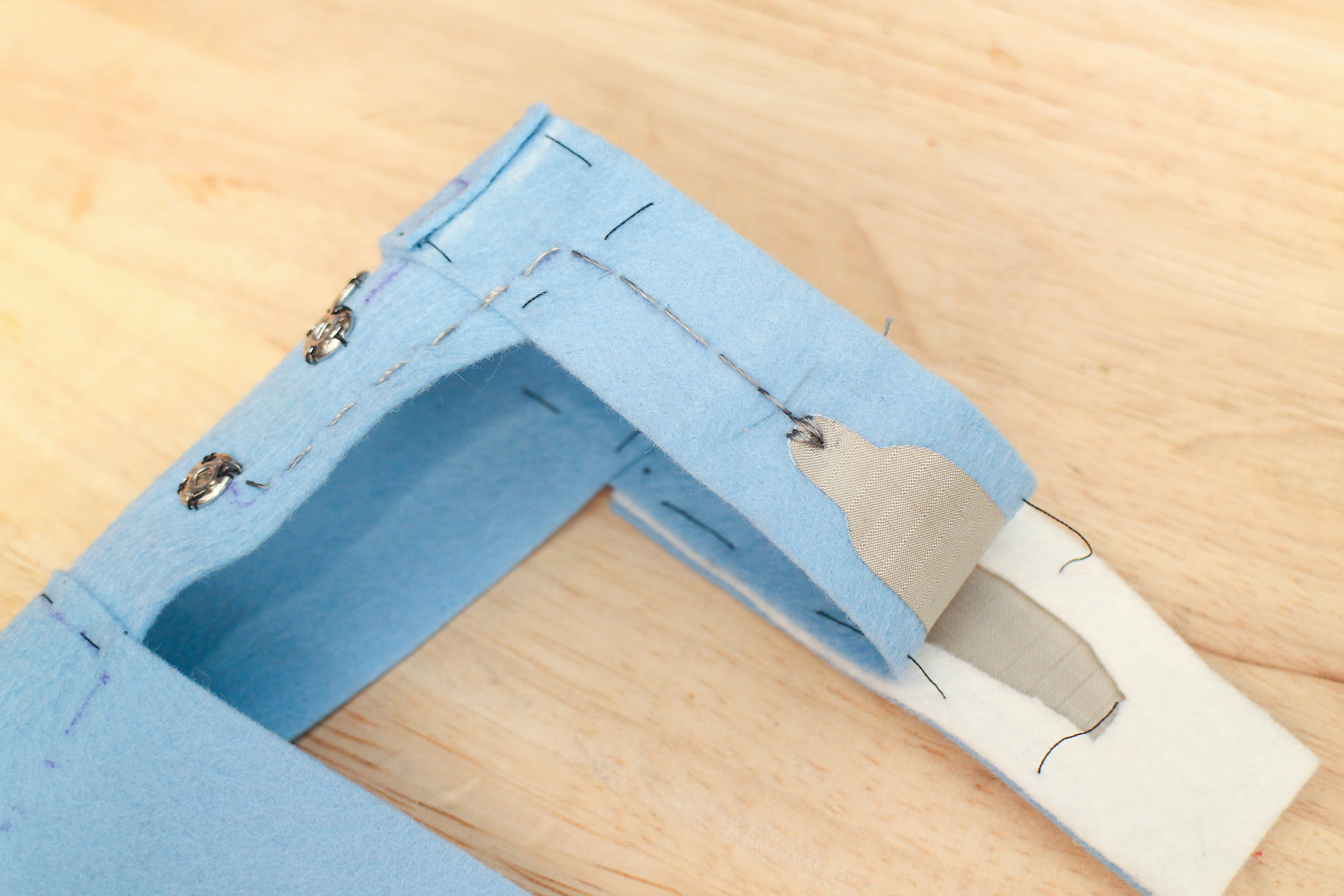
Cut off tails and secure knots on the underside. Also, anywhere it will touch the skin, cover any exposed conductive thread, using more fabric or fusible interfacing. Skin is conductive too and gets even more so when a person perspires.
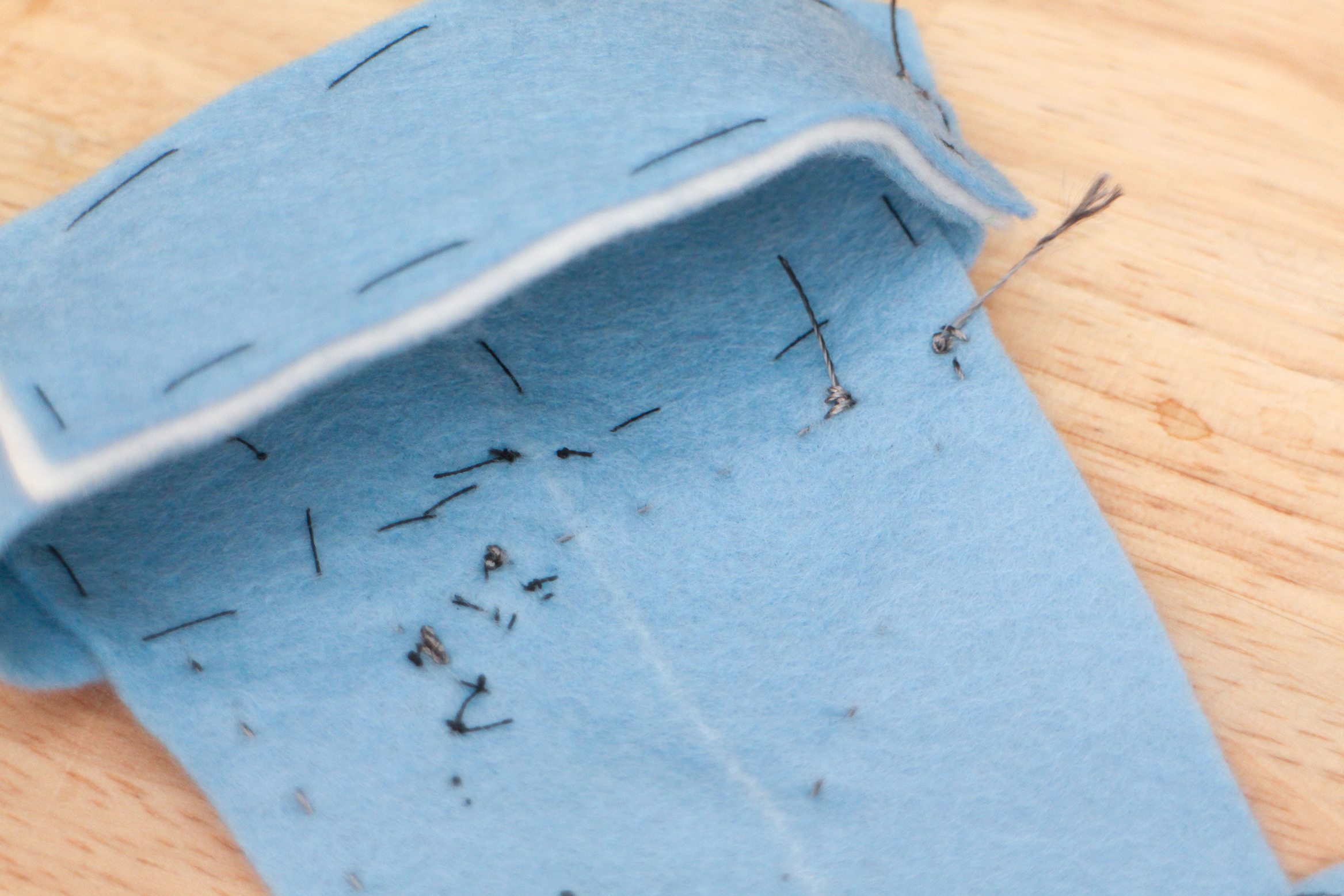
Long tails begging to be cut.
Use fabric glue on and around each knot to secure.
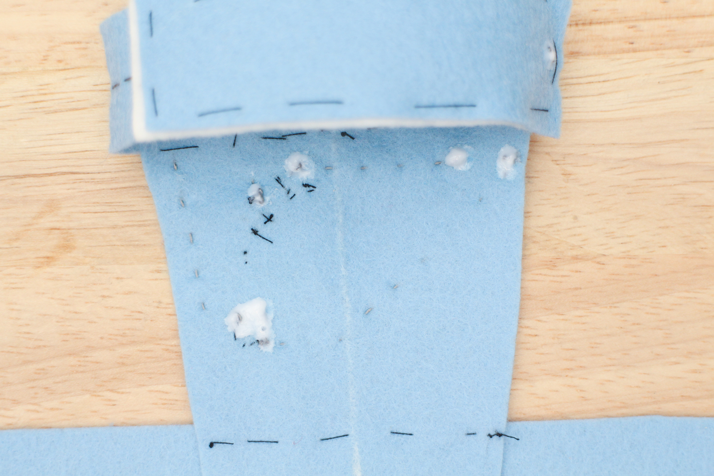
Glue drying over knots.