Key : 🔹 discussion 🔸 lecture ⚡ demo/activity 🍕 lunch
🔹 Compile questions for Sara and her family
🔹 Meet Sara and family via video chat
⚡ Arduino 101
Intro to Hardware
- what is an Arduino?
- different kinds of Arduinos
Terminology
Intro to the software
Digital Input and Output
- blink
- button (how to make a soft switch)
🔸 Prototyping Wearables
- what’s in a wearable prototyping tool kit?
- key points to address when prototyping wearables
- concepts and tools of rapid prototyping
H.W. Design ideas for Sara’s Glove
Arduino 101
Arduino is an open software and hardware platform that has excellent tutorials, support and resources. Built for prototyping interactive projects with endless possibilities.
Getting Started
Download FTDI drivers : Follow Sparkfun’s excellent tutorials below
Additional download For Windows – Install drivers for Arduino Uno board
Intro to Hardware
There are many ways that Arduino compatible boards are packaged. Here are some that will be used in class.
Components of the ProtoSnap Board
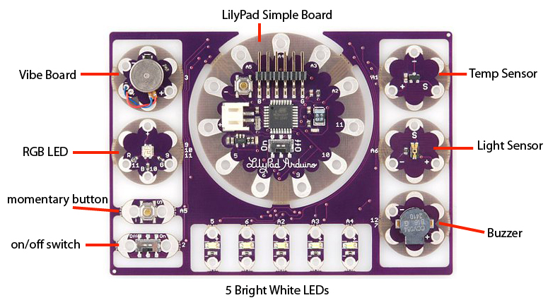
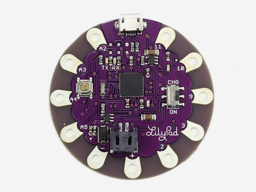
LilyPad Simple Board
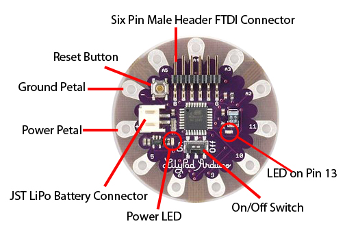
Parts of the LilyPad Simple board
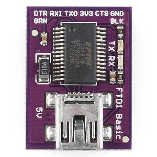
LilyPad Programer FTDI Breakout Board
Additional hardware needed for the LilyPad Simple and Main boards.
LilyPad USB
9 digital : Pins 2, 3, 9, 10, 11, A2/12, A3/13, A4/14 and A5/15
4 PWM : Pins 3, 9, 10 and 11
4 Analog Inputs : A2 – A5
**reference LilyPad Arduino website
A pinout diagram for the LilyPad USB, what you will be using in class.
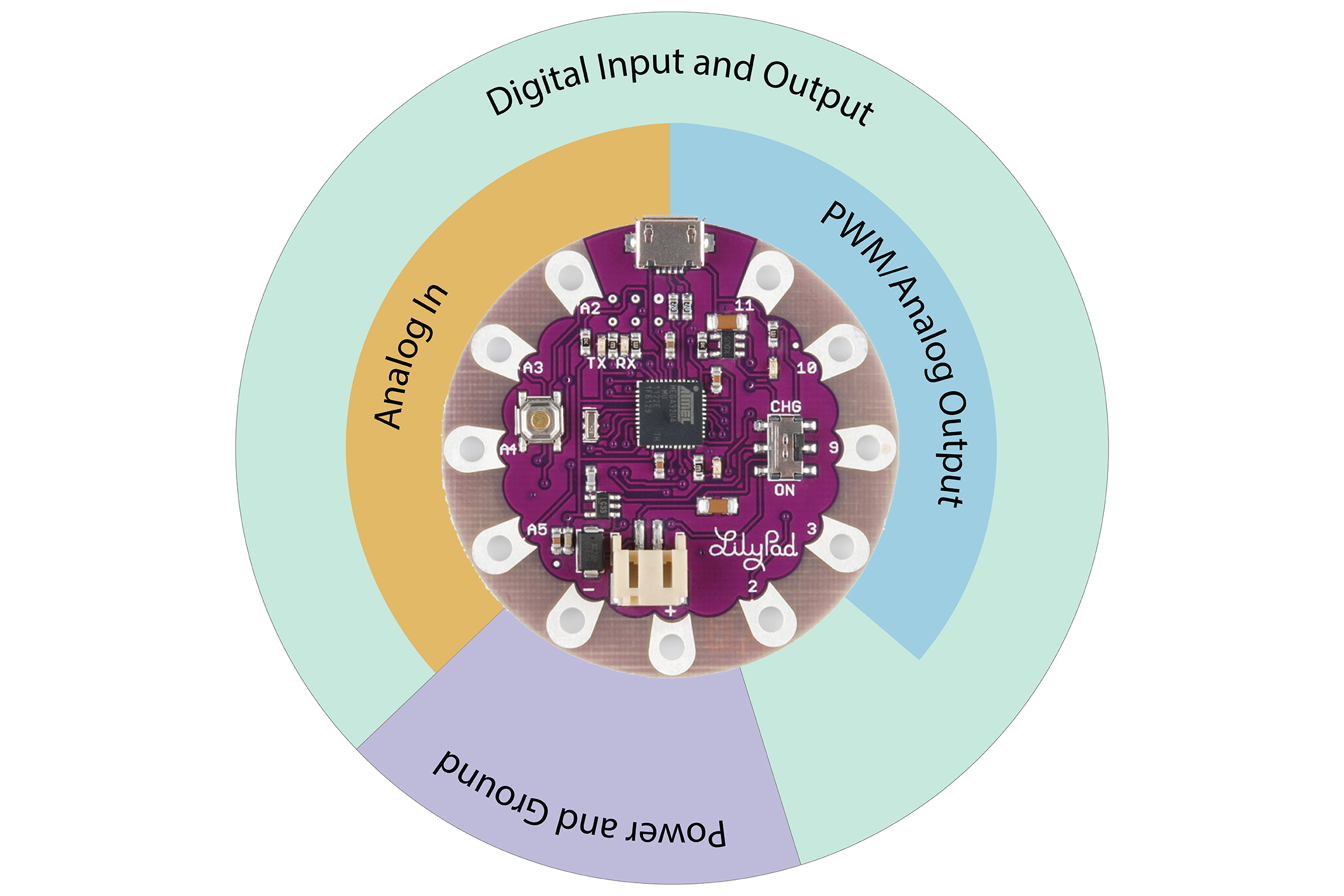
9 Digital : Pins 2, 3, 9, 10, 11, A2, A3, A4 and A5
4 PWM/Analog Output : 3, 9, 10, 11
4 Analog Inputs : A2, A3, A4 and A5
Terms we will be using a lot:
Digital
Analog
Input
Output
PWM
Let’s explore what they mean as they apply to a microcontroller ——>
Digital Input – When you want to sense something in the world, sometimes the only thing you need to know if whether something is true or false. Did the cat hit the toy? Did I clap my hands? Did the door open? These are yes or no questions, binary in logic. Digital inputs are read through a pin and this yes or no (0 or 1) can then be read and used to trigger other events.
Digital Output – Much like how a digital input can sense an action with two states, a digital output can control an action with two states. It can turn on and off something, like a LED.
Analog Input – Sometimes reading two states is not enough, there needs to be some shades of gray between the black and the white. Instead of knowing whether the arm is straight or bent, you can know to what degree it is bent. An analog input on a microcontroller is an input pin that can read variable voltage, typically 0V to 3.3V or 5V.
Analog Out – Analog output can control a component to varying degrees, rather than only 2 states. Think of a light switch being digital on/off and a fader knob as analog. Not only can you switch the light on or off, you can change it’s brightness with analog output.
PWM – This stands for Pulse Width Modulation. This is how a microcontroller, which can really only output digital, tricks us into thinking that it’s outputting analog values. PWM pins swing 0V (off) to it’s highest, let’s say 5V, (on). This on/off pulse creates a square wave. Look for the digital pins on the Arduino board that have a ‘~’ by them, this means they are PWM pins and can be programmed to be analog out.
**references
Intro to Software
Once you have Arduino and the FTDI drivers installed, plug your FTDI breakout board into your LilyPad and the USB cable into the board and into your computer.
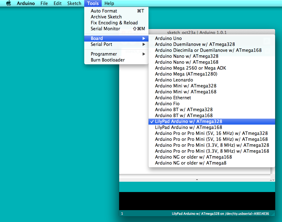
Two things need to happen before you can upload a sketch to the board.
- Tell Arduino what kind of board you have.
Tools > Board > LilyPad Arduino w/ATmega 328 (or whatever board you are using) - Choose the USB to serial port that you computer and board will talk to each other through.
Tools > Serial Port > /dev/tty.usbserial-*******
In Windows, it will be listed as COM*
If nothing is showing up under Serial Port, it means the FTDI drivers did not install properly, close down Arduino, install and reopen.
Use Example Sketches!
Arduino has a bunch of built-in example sketches to get you started. Sketches are programs that you upload to the Arduino to perform a specific task. They are open-source and can be altered and built upon to your liking. The language of Arduino is nicely wrapped C/C++, this means all C/C++ syntax and constructs will work when writing an Arduino sketch.
** Arduino’s FAQ Page
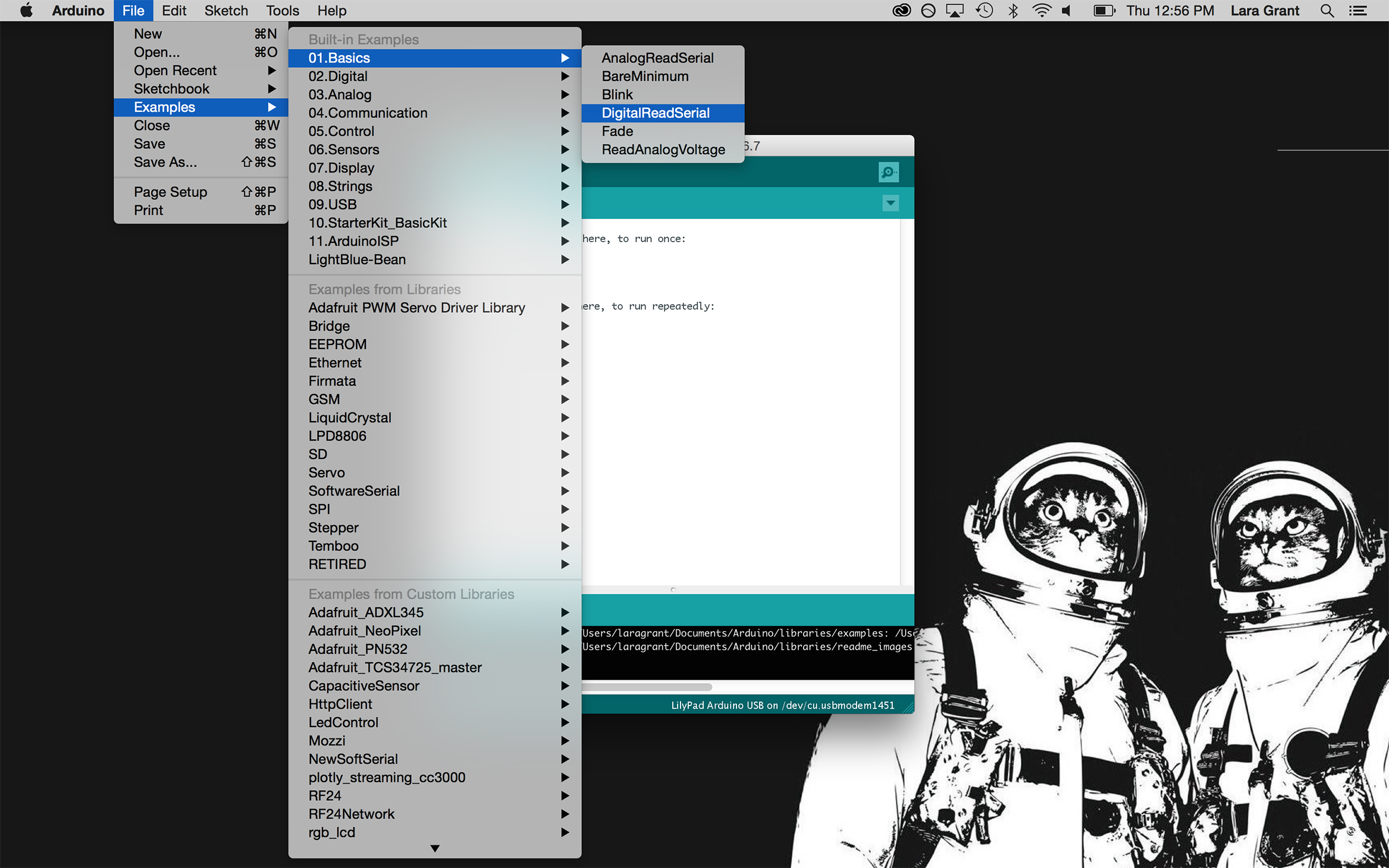
To get to a sketch go to File –> Examples.
There is a long list to choose from. This where we will be working from so we get familiar with Arduino’s environment.
Digital Input and Output
Materials
- microcontroller
- alligator leads
- LED
- USB cord
- switch (handmade)
Digital Output
Hook up LED to pin 3 using alligator clips.
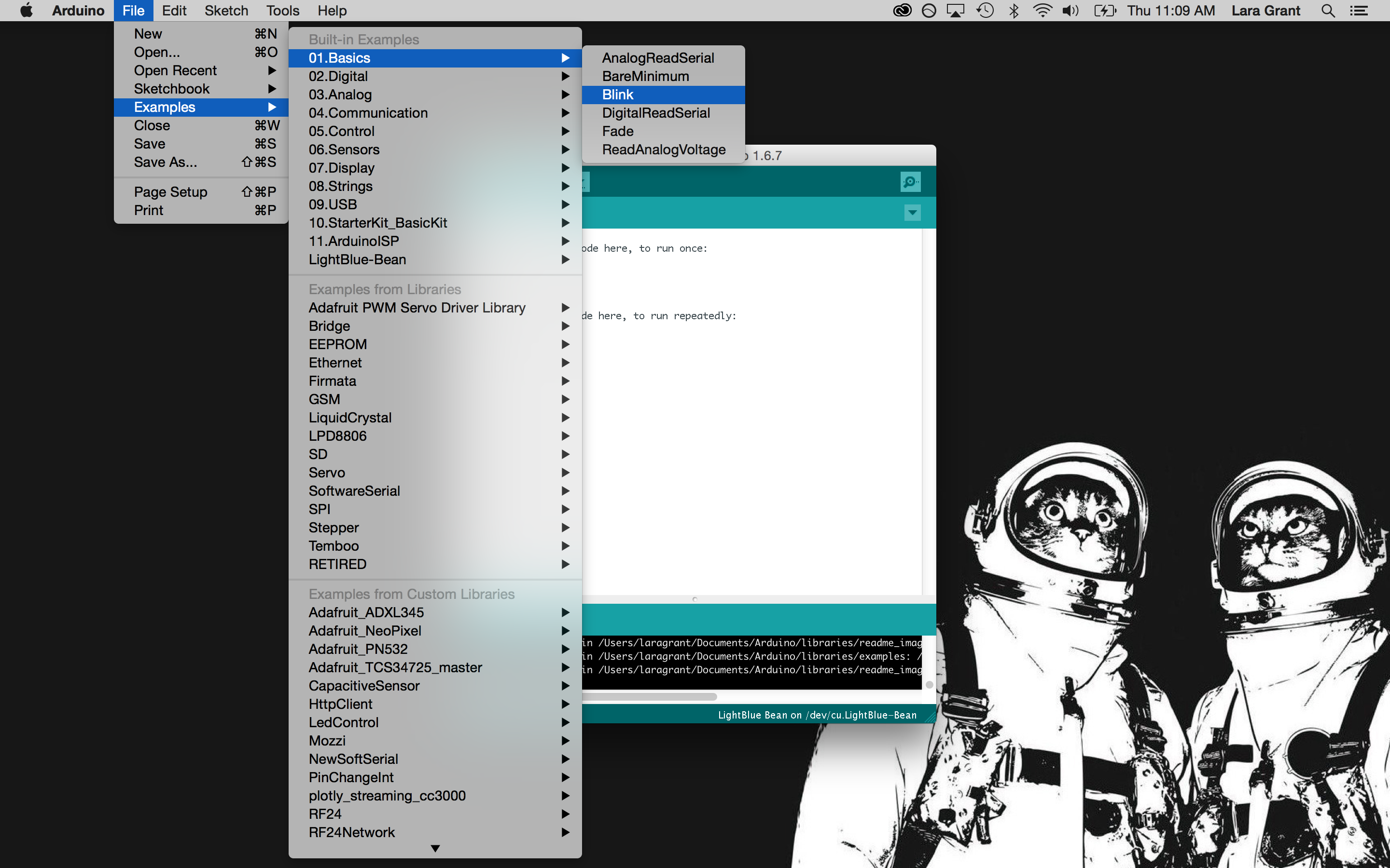
Open Examples > Basics > Blink
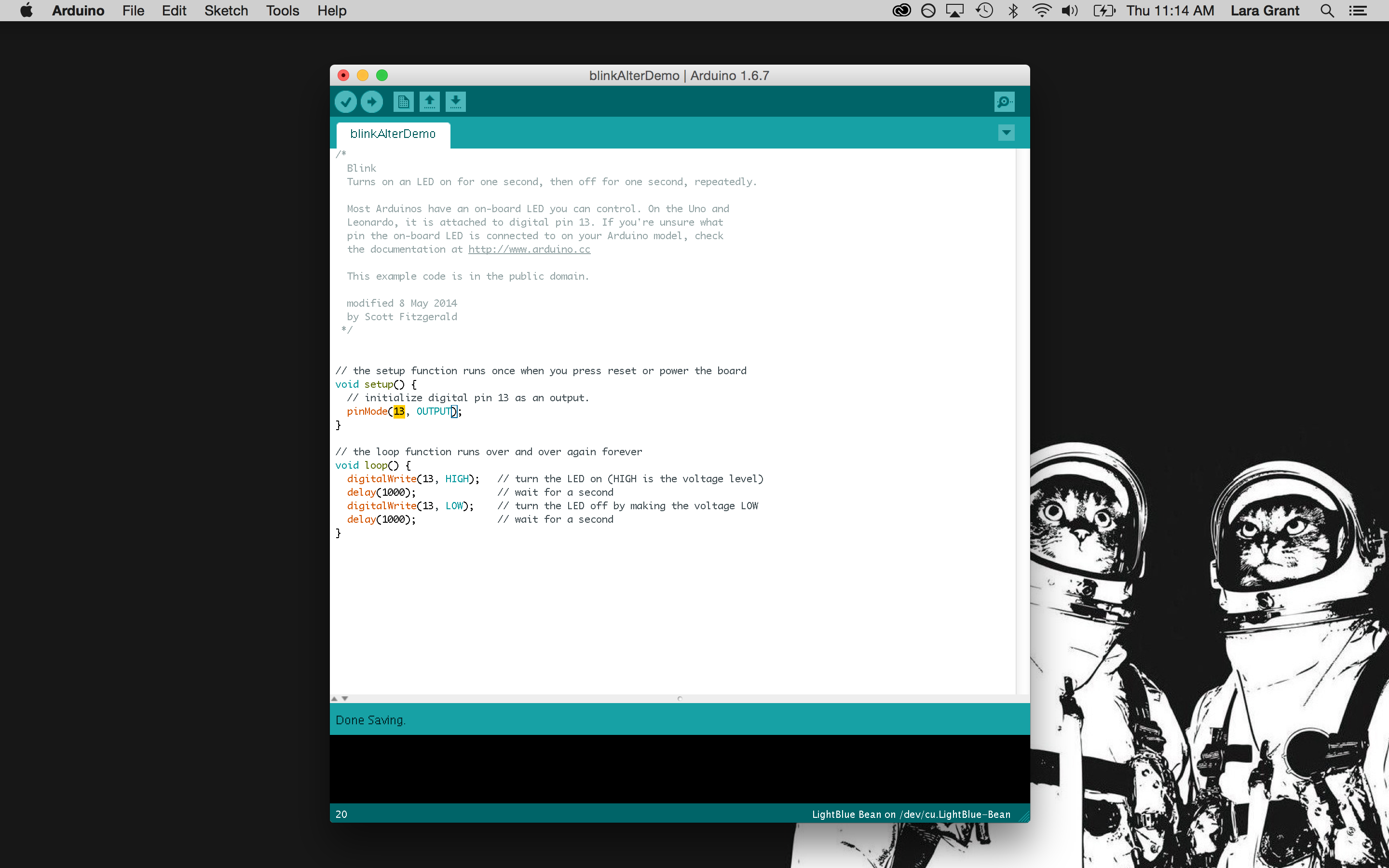
Change LED pin number from 13 -> 3 (or whatever pin you put it on)
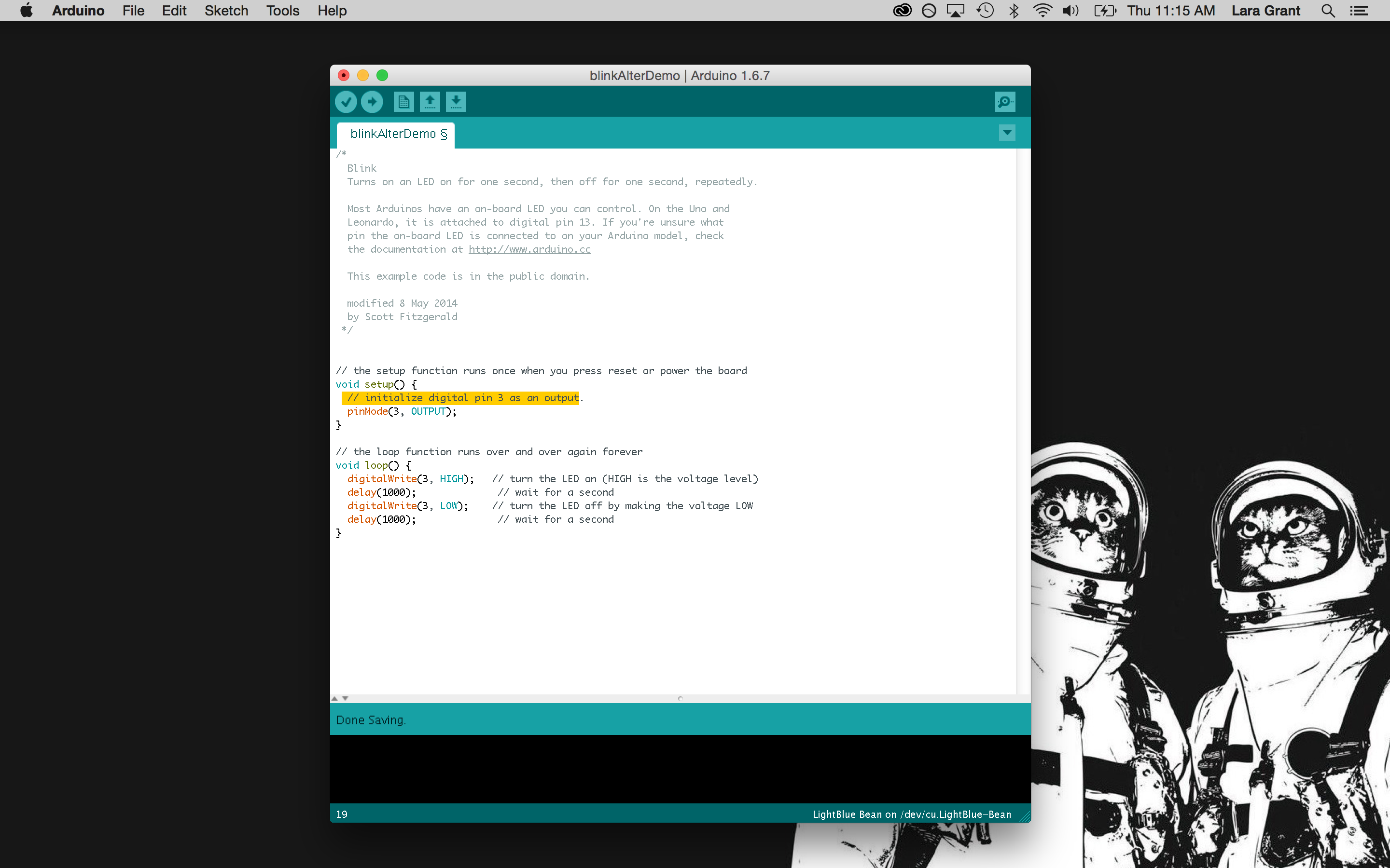
Change comment to reflect pin change. Get used to commenting code! You and others will be thankful for it when trying to figure out what a sketch is programmed to do later on.
Upload Sketch
Blinky success!
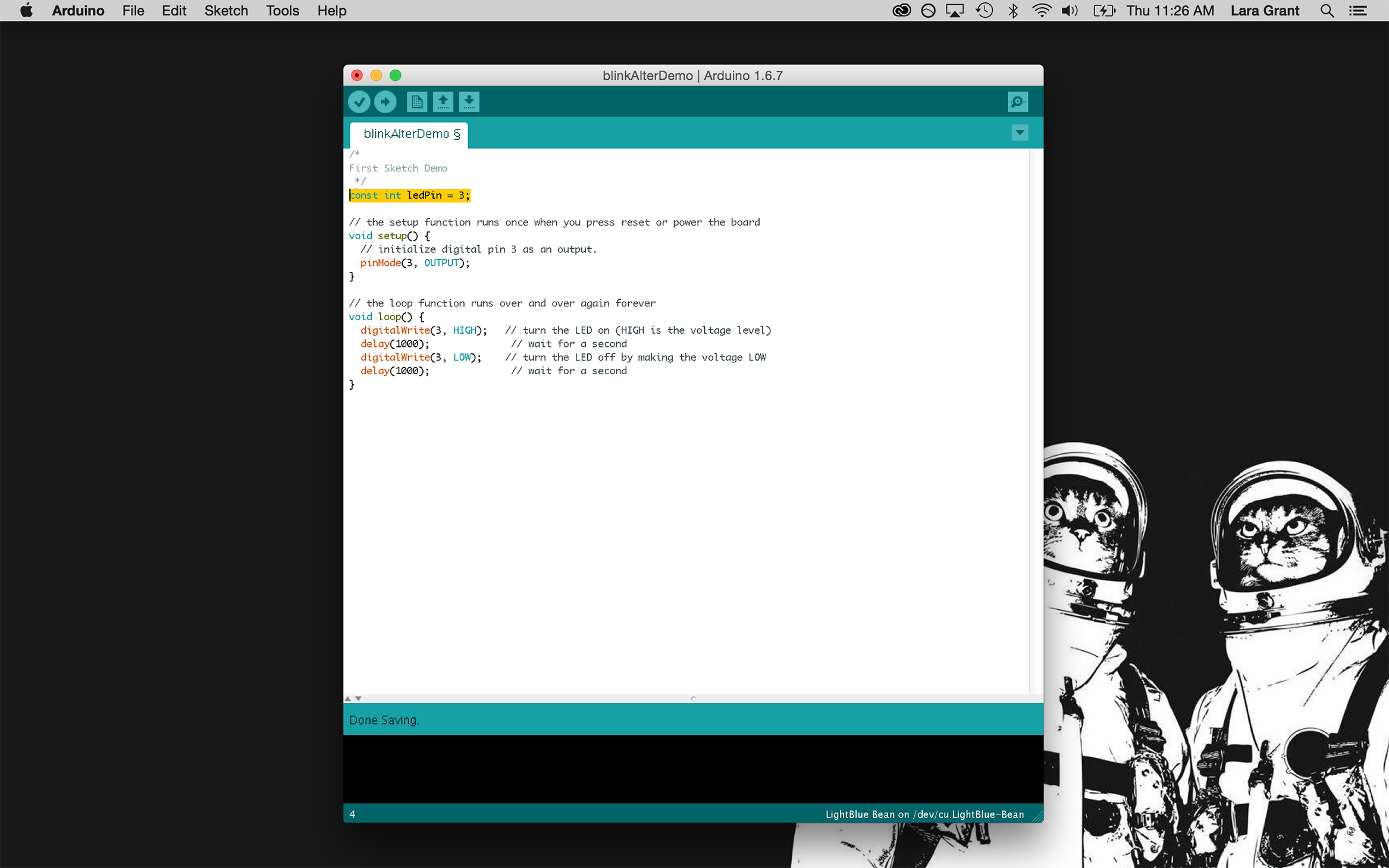
Variables
The number 3 is used a few times in the Blink sketch, what if we wanted to change the pin number later on? We would have to change all 3. The number 3 isn’t very descriptive either, we could be using 3 later on in a simple mathematical operation and it could get confusing. In this sketch, 3 is our LED pin, what if we could just name it that and make it easier to change later on. We can if we create a variable!
A variable can be thought of as a cup that a piece of data is stored in. A name can be written on the outside of the bucket, which we can then use to reference the piece of data it contains. Variables also tell the computer what kind of data it is dealing with, so it can act accordingly.
A variable has a type, name and value.
|
1 |
int ledPin = 3; |
int is short for integer, which is the type of data.
ledPin is the variable’s name we gave it, make it descriptive!
= is how we assign the name a piece of data.
3 is the data we are assigning to the name.
There is another piece of code that needs to be used when declaring the ledPin variable.
|
1 |
const |
This gets put in from of the variable when you know that the value will not be changed later on. This helps protect it from that.
Alter the code by creating a variable for the pin your LED is on.
**reference
const keyword
Arduino variables
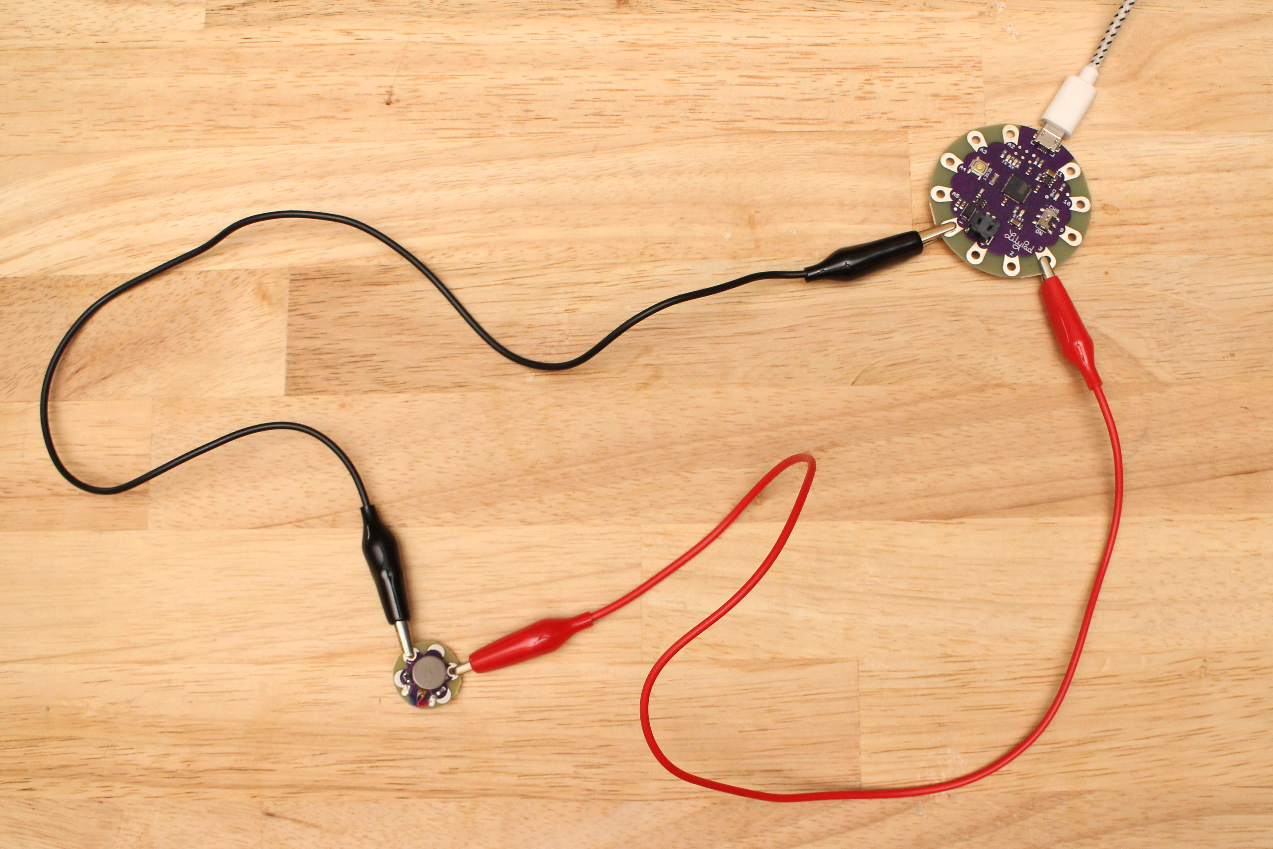
Try hooking up other components, like a vibe board.
Digital Input
To read digital input, we need a digital device. Let’s make a soft switch!
Open digitalRead example, copy, paste and save.
A digital device is something that is either read as on/off, high or low, full voltage (5V) or none (0V). For Arduino to read whether something is high or low on a digital pin, it uses digitalRead().
DigitalRead() takes one parameter, which goes inside the parenthesis. This parameter is the pin number you want to read the device on. In this case, it’s going to be digital pin 2, which assigned to the variable pushButton.
|
1 |
digitalRead(pushButton); |
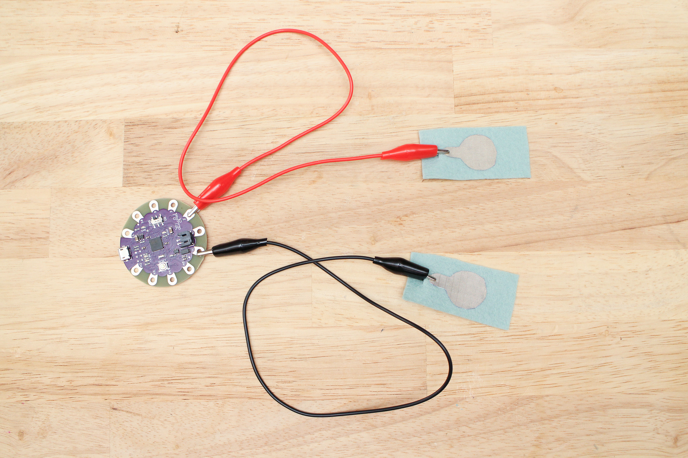
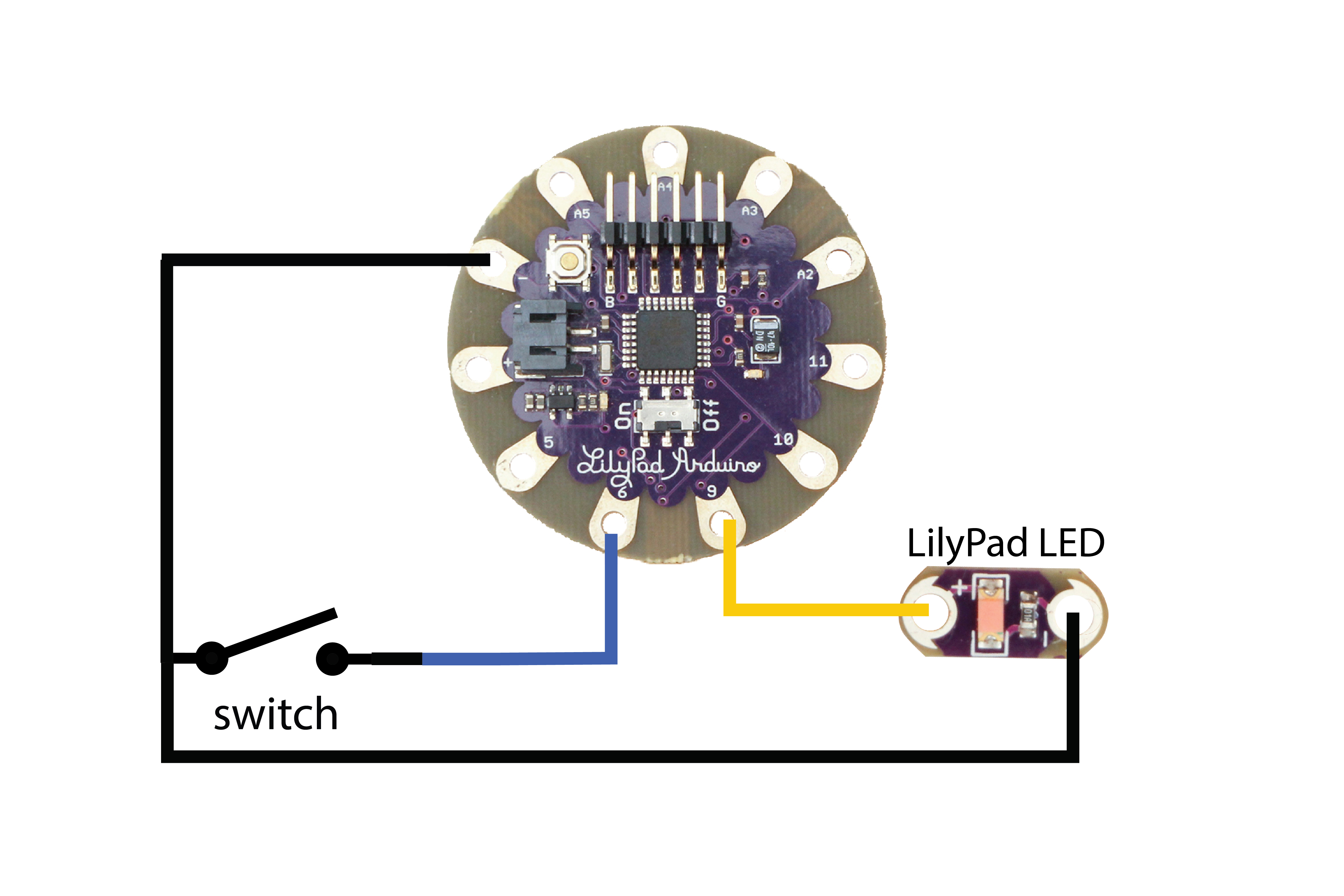
Hook up one side of the switch to pin 2 and the other side to the ground (-) petal.
Upload Sketch
Before moving on, take a look at the sketch again and where it says:
|
1 |
Serial.begin(9600); |
This opens the serial port which is essential to debugging. Debugging simply means to find out what is wrong when the circuit and software is not behaving as you intend it to and fixing it. The microcontroller communicates with your computer over serial and can print out the results of your program when you open the port, with Serial.begin() and when you tell it to print with:
|
1 |
Serial.println(buttonState); |
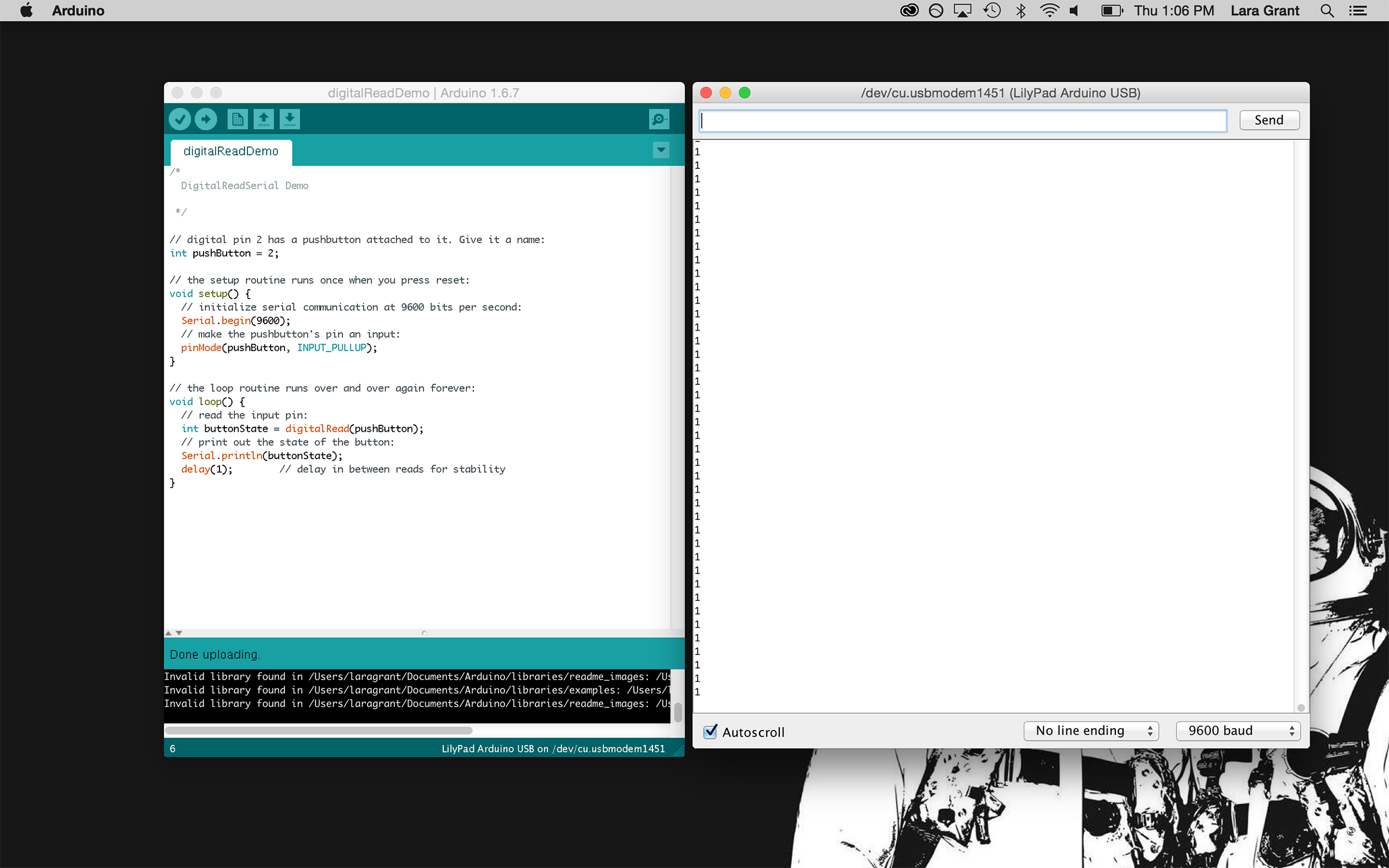
Let’s see this in action. Open up the serial monitor.
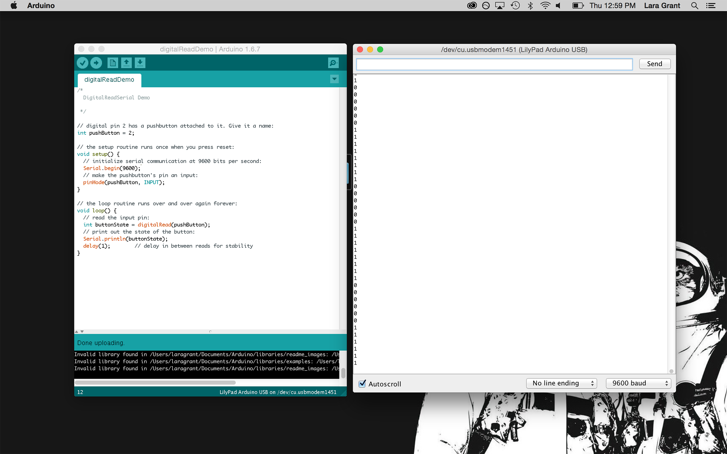
There are a bunch of 0s and 1s. What we want is either a 1 when the switch is pressed or a 0, this looks unstable. This is called a floating pin. When the switch is open, it doesn’t know what value to reference, the pin is left there hanging in the wind. A circuit needs to be closed or connected to power or ground somehow, so it always has a voltage reference. Right now, it doesn’t have one. What will help this situation and how do we give it a reference?
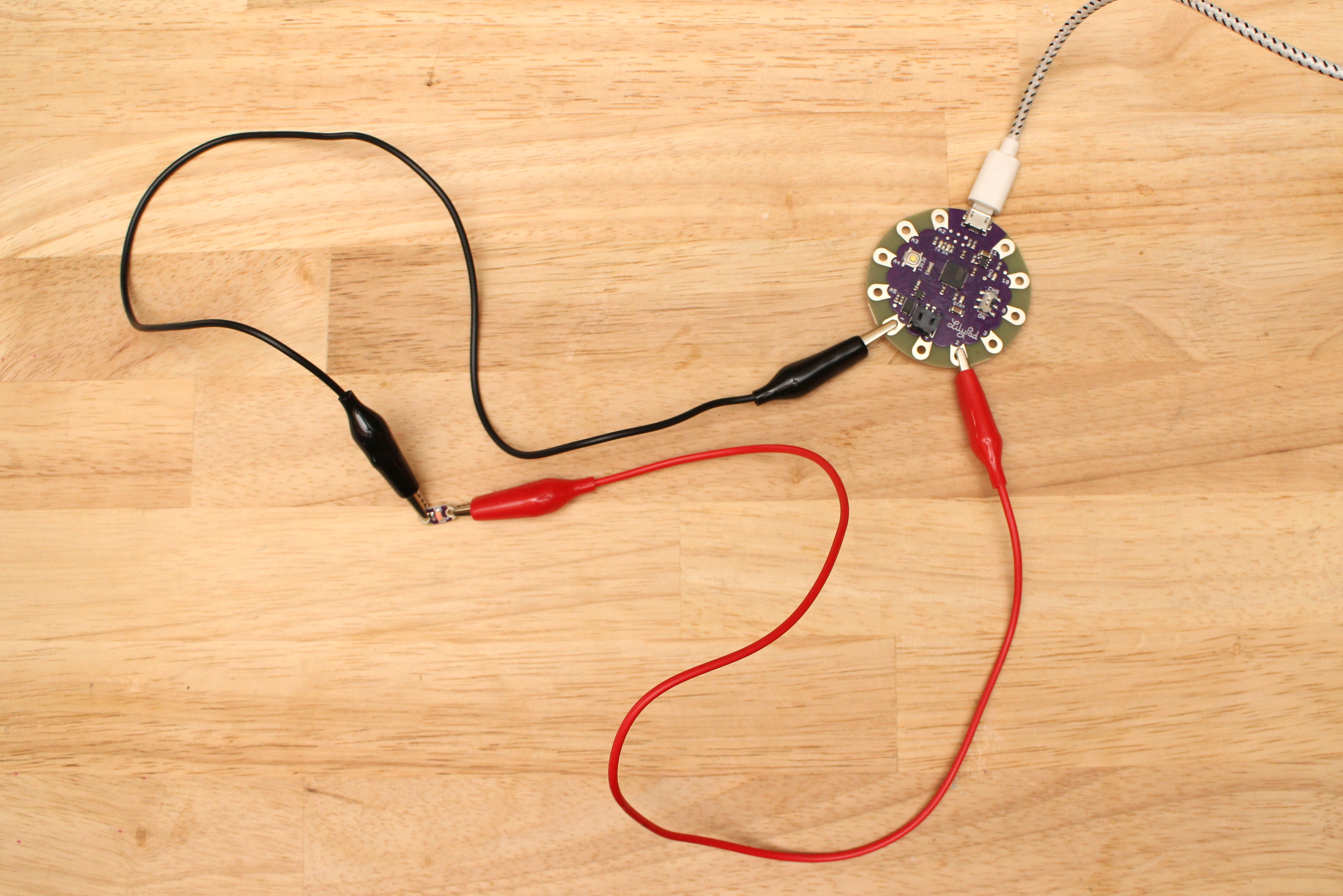
The answer is a pull-up or pull-down resistor. Let’s start with a pull-down resistor. Hook up a circuit using a breadboard or alligator clips.
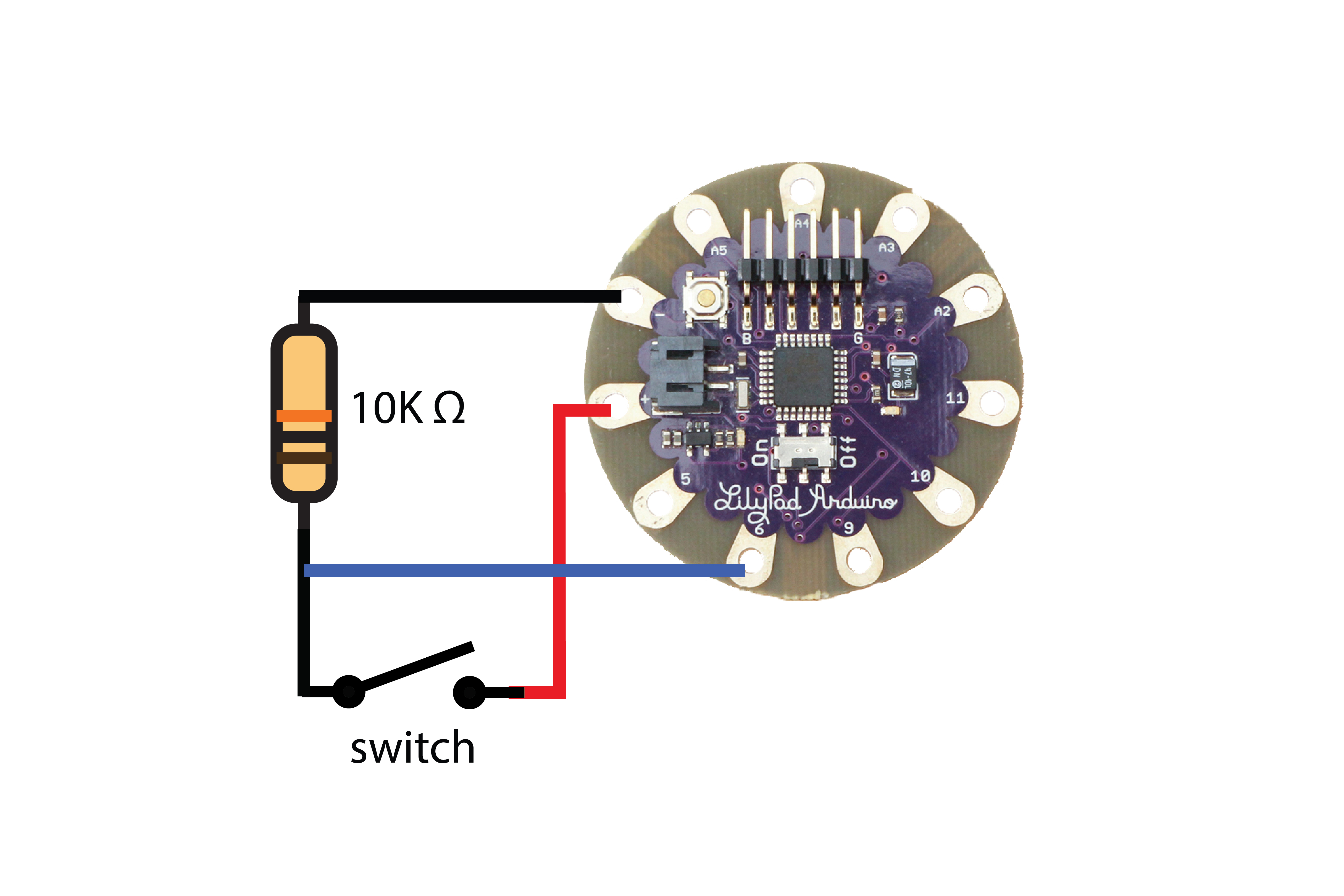
The 10K ohm resistor is connected between digital pin 6 and ground. When the switch is open, it pulls the voltage down to almost 0, hence it’s name, pull-down resistor. This means we will see a 0 in our serial monitor when the switch is open.
When the switch is closed, it swings to high, 5 volts that comes from the power petal. This will print a 1 in the serial monitor.
Now, let’s use a pull-up resistor. This is what the circuit looks like if we want the circuit to be pulled to 5 volts.
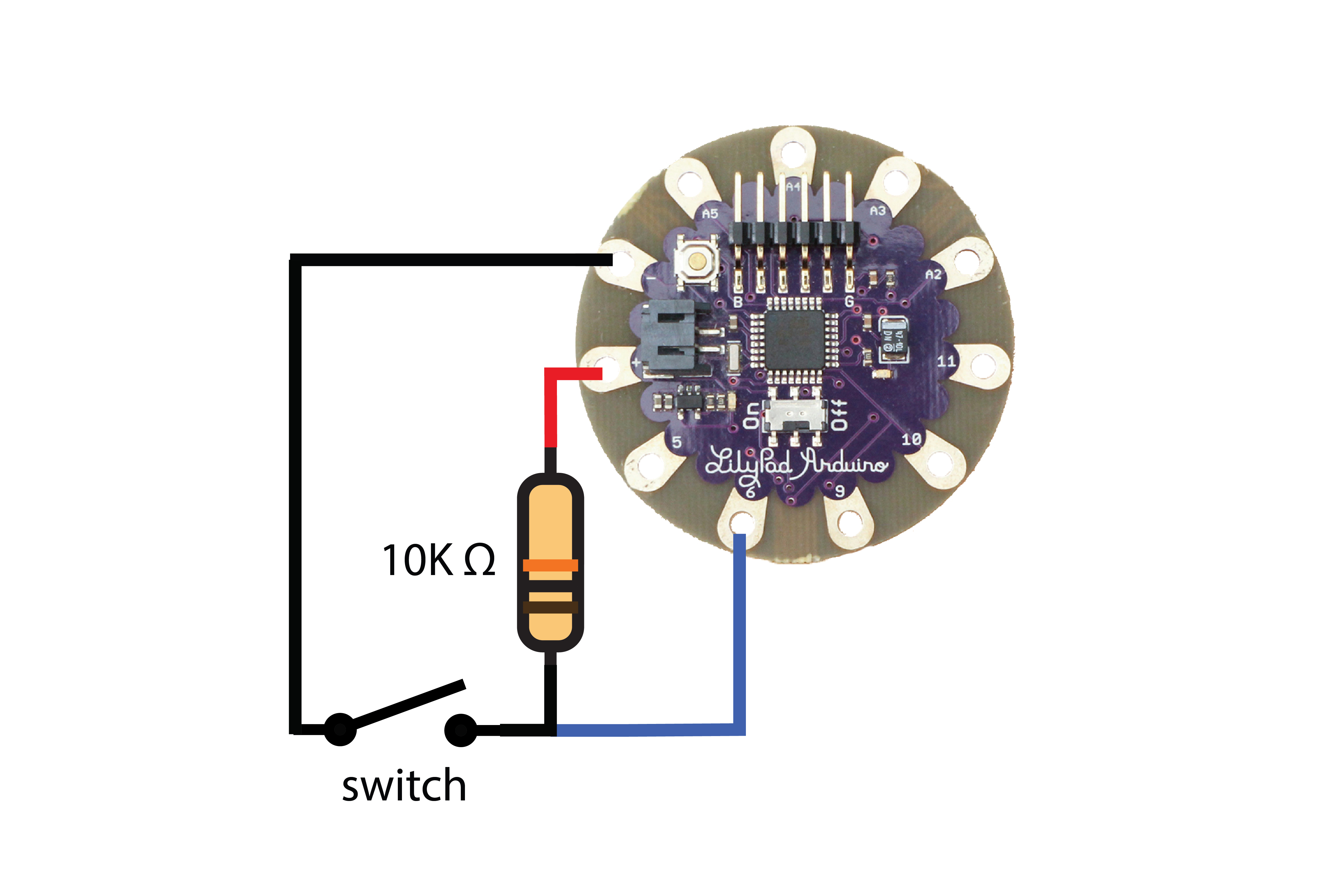
But wait! We don’t need to add a resistor, because the LilyPad Arduino and almost every Arduino have built-in pull-ups that can be enabled through software. This simplifies the circuit, which is really helpful when using alligator leads to make all the connections.
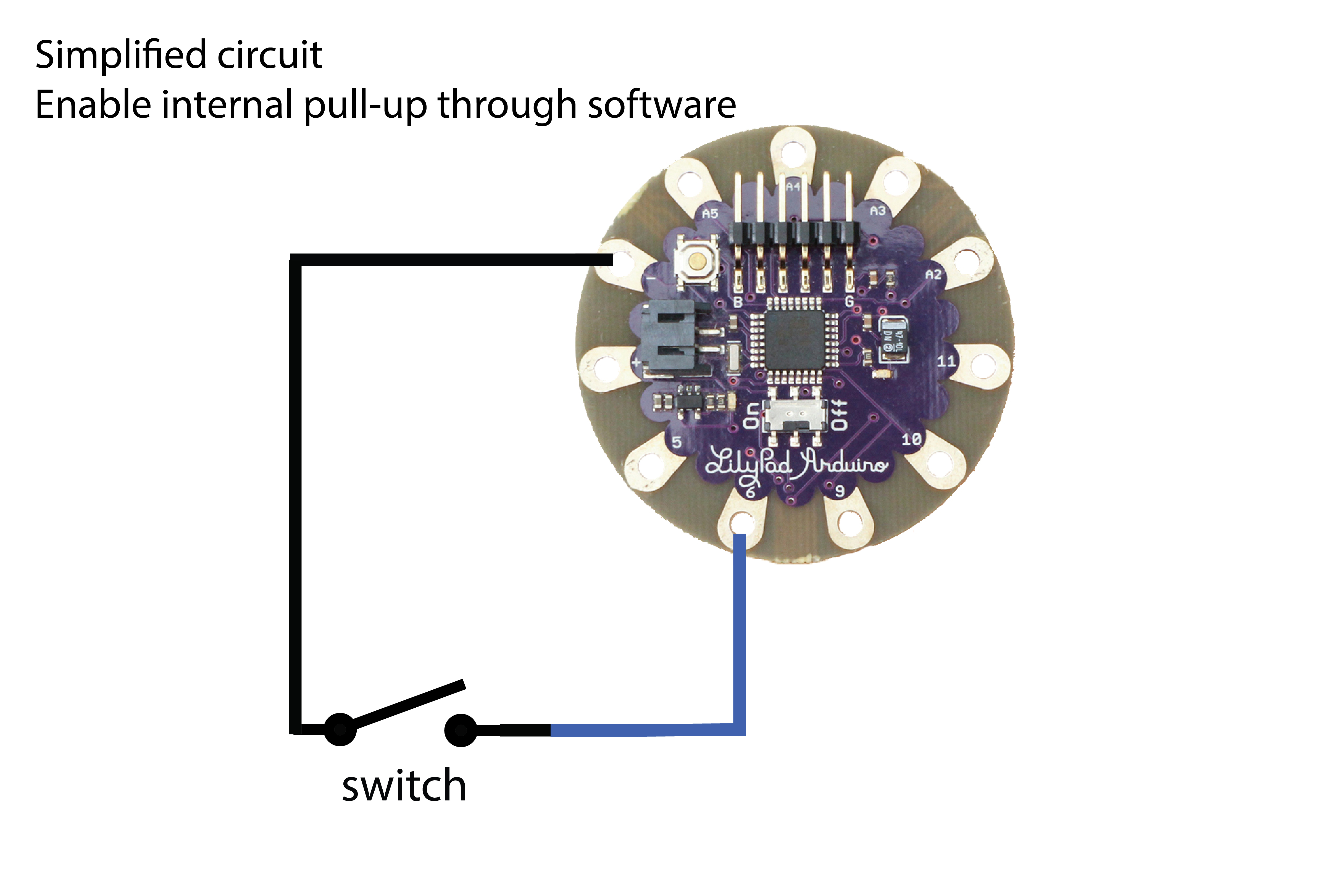
Final circuit when using pull-up resistor the Arduino provides.
Change this piece of the sketch to enable the internal pull-up resistor.
|
1 |
pinMode(pushButton, INPUT); |
to
|
1 |
pinMode(pushButton, INPUT_PULLUP); |
Upload Sketch
Combining Input and Output
Open Examples > Digital > Button
Change pin 13 to pin LED
Enable serial port with:
|
1 |
Serial.begin(9600); |
|
1 |
Serial.println(buttonState); |
Enable internal pull-up resistor
Upload Sketch
LED is on when switch is open, off when closed.
Adjust code to make it off when open and on with closed.